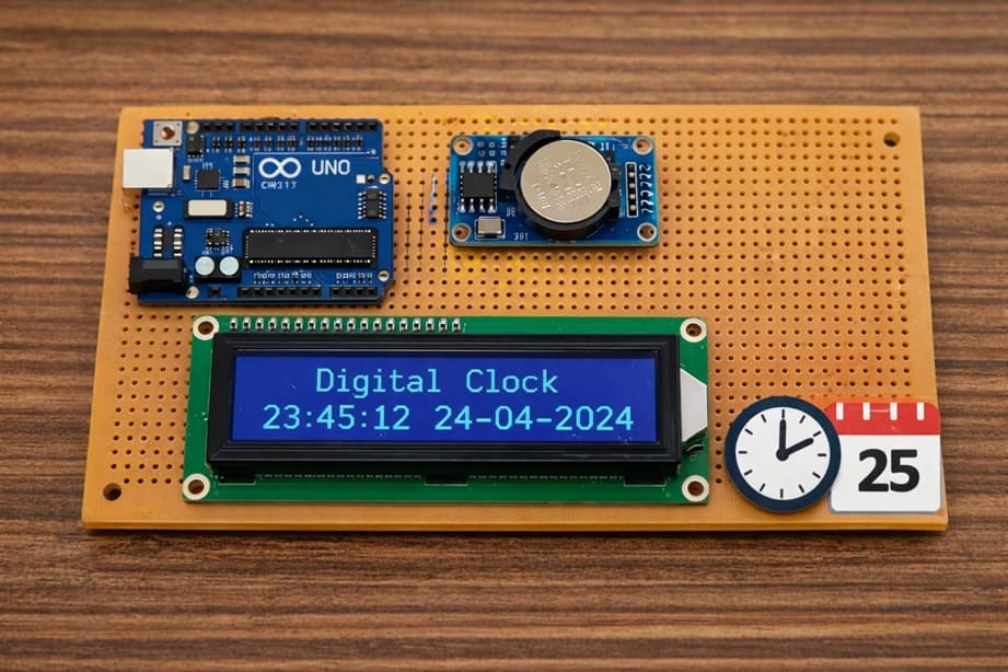
Arduino digital Clock with DS1302 RTC module
Tutorial plan
1- Objective of the project
2- Required Components
3- Circuit Connections of system
4- Arduino Clock program
Objective of the project
Objective :
The objective of this project is to design and build a digital clock using an Arduino Uno, a DS1302 RTC Module, and a LCD I2C Display. The project aims to display the current time and date in real time on the LCD screen. It helps users learn how to interface a real-time clock module with Arduino and how to display information using an I2C LCD display. This project is useful for understanding embedded systems, time management applications, and electronic display control.
Functionment (How it Works) :
The system works by using the Arduino as the main controller. The DS1302 RTC module keeps track of the current time and date continuously, even when the Arduino is powered off, thanks to its backup battery. When the Arduino is powered on, it communicates with the RTC module to read the stored time and date values.
The Arduino then processes this information and sends it to the LCD I2C display using the I2C communication protocol. The LCD screen shows the time (hours, minutes, seconds) and the date (day, month, year) clearly for the user. The Arduino updates the display every second to ensure that the clock always shows the correct current time.
This project demonstrates how a microcontroller can interact with a real-time clock module and a display to create a practical and reliable digital clock system.
Required Components
1. Arduino UNO
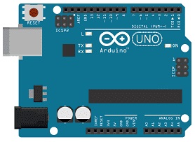
The Arduino board is the main controller of the project. It reads the current time and date from the RTC module and sends this information to the LCD display. It also controls the communication between all connected components. The Arduino executes the program instructions and ensures the clock updates continuously.
2. DS1302 RTC Module
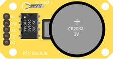
The Maxim Integrated DS1302 RTC (Real-Time Clock) module is used to keep track of the current time and date. It can store seconds, minutes, hours, day, month, and year. The module has a backup battery, which allows it to continue keeping time even when the Arduino is turned off. This ensures accurate and continuous timekeeping.
3. LCD Display with I2C Module

The LCD I2C display is used to show the date and time to the user. It uses the I2C communication protocol, which requires only two wires (SDA and SCL), making connections simpler. The display can show text such as the day, date, and current time in real time.
4. Jumper Wires

Jumper wires are used to connect the Arduino, RTC module, and LCD display together. They allow electrical signals and power to flow between the components.
Circuit Connections of system
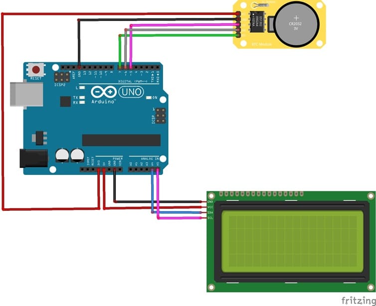
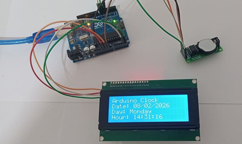
1- Connection of DS1302 RTC Module to Arduino UNO
| DS1302 RTC | Arduino UNO |
|---|---|
| CLK | pin 5 |
| DAT | pin 6 |
| RST | pin 7 |
| VCC | 5V |
| GND | GND |
2- Connection of LCD I2C display to Arduino UNO
| LCD display | Arduino UNO |
|---|---|
| VCC | 5V |
| GND | GND |
| SDA | pin A4 |
| SCL | pin A5 |
Arduino Clock program
This program creates a digital clock using an Arduino Uno, a DS1302 RTC Module, and an LCD I2C Display. Its main purpose is to read the current date and time from the RTC module and display them clearly on the LCD screen.
You need to install this libraries :
LiquidCrystal_I2C for I2C LCD screen
ErriezDS1302-master for DS1302 RTC module
|
1 2 3 4 5 6 7 8 9 10 11 12 13 14 15 16 17 18 19 20 21 22 23 24 25 26 27 28 29 30 31 32 33 34 35 36 37 38 39 40 41 42 43 44 45 46 47 48 49 50 51 52 53 54 55 56 57 58 59 60 61 62 63 64 65 66 67 68 69 70 71 72 73 74 75 76 77 78 79 80 81 82 83 84 85 86 87 88 89 90 91 92 93 94 95 96 97 98 99 100 101 102 103 104 105 106 107 108 109 110 111 112 113 114 115 116 117 118 119 120 121 122 123 124 125 126 127 128 129 130 131 132 133 134 135 136 137 138 139 140 141 142 143 144 145 146 147 148 149 150 151 152 153 154 155 156 157 158 159 160 161 |
// Include the library for the DS1302 RTC module #include <ErriezDS1302.h> // Include the library for the I2C LCD display #include <LiquidCrystal_I2C.h> // =============================== // DS1302 RTC Configuration // =============================== // Define the pins used for the RTC module #define CLK_PIN 5 // Clock pin #define IO_PIN 6 // Data pin #define CE_PIN 7 // Chip Enable pin // Create the RTC object using the defined pins ErriezDS1302 rtc(CLK_PIN, IO_PIN, CE_PIN); // =============================== // LCD I2C 20x4 Configuration // =============================== // I2C address = 0x27 // LCD has 20 columns and 4 rows LiquidCrystal_I2C lcd(0x27, 20, 4); // Array containing the names of the days of the week const char* jours[] = { "Sunday", "Monday", "Tuesday", "Wednesday", "Thursday", "Friday", "Saturday" }; // =============================== // Setup function (runs once at startup) // =============================== void setup() { // Start serial communication at 9600 baud rate Serial.begin(9600); // Initialize the LCD display lcd.init(); // Start the LCD lcd.backlight(); // Turn on the backlight lcd.clear(); // Clear the screen // Initialize the RTC module if (!rtc.begin()) { // Display an error message if RTC is not detected lcd.setCursor(0, 0); lcd.print("RTC not detected"); // Stop the program execution while (1); } // Enable the RTC clock rtc.clockEnable(true); // ⚠️ Set the time ONLY ONCE, then comment this line // Format: // hour, minute, second, day, month, year, weekday rtc.setDateTime(14, 30, 0, 8, 2, 2026, 1); // Example: Monday // Display confirmation message lcd.setCursor(0, 0); lcd.print("RTC initialized"); delay(2000); // Clear the screen lcd.clear(); } // =============================== // Loop function (runs continuously) // =============================== void loop() { // Declare variables to store date and time values uint8_t hour, min, sec, day, mon, wday; uint16_t year; // Read date and time from the RTC module if (rtc.getDateTime(&hour, &min, &sec, &day, &mon, &year, &wday)) { // Display the project title lcd.setCursor(0, 0); lcd.print("Arduino Clock"); // =============================== // Display the date // =============================== lcd.setCursor(0, 1); lcd.print("Date: "); // Add leading zero if day < 10 if (day < 10) lcd.print("0"); lcd.print(day); lcd.print("/"); // Add leading zero if month < 10 if (mon < 10) lcd.print("0"); lcd.print(mon); lcd.print("/"); // Display the year lcd.print(year); // =============================== // Display the day of the week // =============================== lcd.setCursor(0, 2); lcd.print("Day: "); // Display the day name from the array lcd.print(jours[wday]); // =============================== // Display the time // =============================== lcd.setCursor(0, 3); lcd.print("Hour: "); // Add leading zero if hour < 10 if (hour < 10) lcd.print("0"); lcd.print(hour); lcd.print(":"); // Add leading zero if minute < 10 if (min < 10) lcd.print("0"); lcd.print(min); lcd.print(":"); // Add leading zero if second < 10 if (sec < 10) lcd.print("0"); lcd.print(sec); } else { // Display an error message if reading fails lcd.clear(); lcd.setCursor(0, 0); lcd.print("Error RTC"); } // Wait 1 second before the next update delay(1000); } |
0 comment
Leave a comment
Passion for robotics

Recent tutorials


Robotics workshop

Polpular tutorials


Making robots

Most commented tutorials


Robotic arm

Categories
Smart Home