Control a lamp with ESP8266 NodeMCU and push button
Tutorial plan
1- Objective of this tutorial
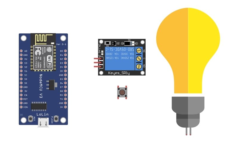
2- The necessary components
3- Mounting ESP8266 NodeMCU card with lamp and push buttons
4- Program ESP8266 NodeMCU with MicroPython
Objective of this tutorial
The objective of this tutorial is to control a lamp using the ESP8266 NodeMCU board and a push button. By pressing the button, the user can turn the lamp ON or OFF through a relay module connected to the NodeMCU. This project demonstrates how to use digital input (push button) and digital output (relay controlling a 220V lamp) with the ESP8266.
Through this tutorial, you will learn how to:
- connect a relay module to the ESP8266 NodeMCU to control a high-voltage lamp safely.
- use a push button as a digital input to trigger actions.
- write a MicroPython program to detect button presses and toggle the lamp’s state.
- understand the basic principles of home automation using microcontrollers.
The necessary components
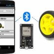
1. ESP8266 NodeMCU board:
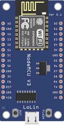
The NodeMCU is a microcontroller board based on the ESP8266 Wi-Fi chip. It can be programmed using MicroPython or Arduino IDE. In this project, it acts as the main controller that reads the state of the push button and controls the relay to turn the lamp ON or OFF.
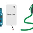
2. Lamp (220V AC):

The lamp is the load we want to control. It operates on 220V AC and will be switched ON or OFF by the relay module under the control of the NodeMCU.
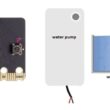
3. Relay module:
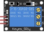
The relay module acts as an electrical switch that allows the low-voltage NodeMCU to safely control a high-voltage device such as a lamp. When the NodeMCU sends a HIGH signal to the relay, the relay activates and closes the circuit to power the lamp.
4. Push button:
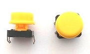
The push button serves as a manual control input. When pressed, it sends a signal to one of the digital input pins of the NodeMCU, which then changes the state of the lamp (ON or OFF).
4. Power Supply (220V AC)

It provides the electrical power needed to operate the lamp.
Wiring:

They safely connect a 220V AC lamp to a relay module that is controlled by the ESP8266 NodeMCU board.
5. Breadboard:

The breadboard allows easy assembly of the components without soldering. It helps in making temporary connections between the NodeMCU, button, and relay.
6. Jumper wires:
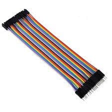
These wires are used to connect different components together on the breadboard and to the NodeMCU. They ensure proper electrical communication between the microcontroller, relay, and button.
Mounting ESP8266 NodeMCU card with lamp and push buttons
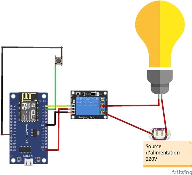
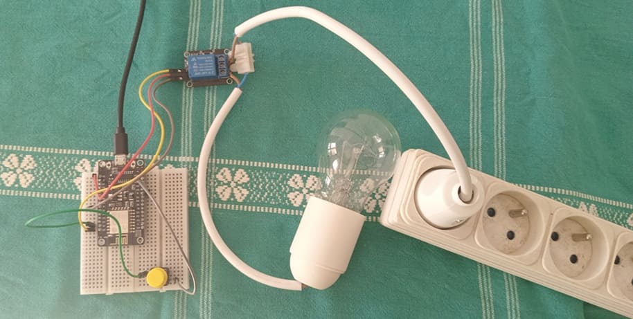
1- Connect the Relay to the ESP8266 board:
- Connect the relay's control pin (S) to pin D0 (GPIO16) of ESP8266 board.
- Connect the pin (+) of relay to pin 3.3V of ESP8266 board.
- Connect the relay's ground pin (GND) to the ESP8266's GND.
2- Connect the push button to the ESP8266 board:
- Connect one leg of the push button to pin D1 (GPIO5) of the ESP8266 board.
- Connect another leg of the push button to pin GND of the ESP8266 board.
3- Connect the Lamp and the power supply to the Relay:
- Connect one of the power supply's wires to the relay's common (COM) terminal.
- Connect the phase wire of the the lamp to the normally open (NO) terminal of the relay.
- Connect the neutral wire of the power supply directly to the neutral wire of the lamp.
Program ESP8266 NodeMCU with MicroPython
You can connect to your ESP8622 board using a serial terminal (e.g., PuTTY, minicom) or use a tool like Thonny to write and execute MicroPython code.
Here's a simple example code to turn on the lamp when the push button is pressed:
1- Import the necessary modules:
|
1 2 |
import machine from machine import Pin import time |
2- Configure the pins (GPIO) for the push button and the relay who will light the lamp:
|
1 2 |
button = machine.Pin(5, machine.Pin.IN, machine.Pin.PULL_UP) relay_lamp=Pin(16, Pin.OUT) |
Make sure to connect the push button to GPIO pin D1 (GPIO5) and the relay to GPIO pin D0 (GPIO16).
3- Create a variable to keep the state of the relay (0 if the lamp is off and 1 if the lamp is on)
|
1 |
relay_lamp_state=0; |
Create a loop to monitor the pushbutton status and turn the lamp on/off accordingly:
|
1 2 3 4 5 6 7 8 9 10 11 12 13 14 15 |
while True: first = button.value() time.sleep(0.01) second = button.value() if first and not second: print('Button pressed!') if (relay_lamp_state==0): relay_lamp.value(1) relay_lamp_state=1 else: relay_lamp.value(0) relay_lamp_state=0; time.sleep(0.5) elif not first and second: print('Button released!') |
Here is the complete program in Micropython:
|
1 2 3 4 5 6 7 8 9 10 11 12 13 14 15 16 17 18 19 20 21 |
import machine from machine import Pin import time button = machine.Pin(22, machine.Pin.IN, machine.Pin.PULL_UP) relay_lamp=Pin(23, Pin.OUT) relay_lamp_state=0; while True: first = button.value() time.sleep(0.01) second = button.value() if first and not second: print('Button pressed!') if (relay_lamp_state==0): led_rouge.value(1) relay_lamp_state=1 else: led_rouge.value(0) relay_lamp_state=0; time.sleep(0.5) elif not first and second: print('Button released!') |
When the button is pressed (the state is low), the lamp lights up. If the button is pressed another time, the lamp turns off. The 0.5 second delay is used to prevent pushbutton bounce, which can cause multiple button activations with a single press.
This simple example demonstrates how to use MicroPython to control a lamp using a relay and a push button with an ESP8266 board.
0 comment
Leave a comment
Passion for robotics

Recent tutorials
Robotics workshop

Polpular tutorials


Making robots

Most commented tutorials


Robotic arm

Categories
Smart Home