Control Two LEDs Using an IR Remote and ESP8266 NodeMCU
Tutorial plan
1- Objective of the tutorial
2- The necessary components
3- Assembly of the electronic system
4- Program ESP8266 NodeMCU with MicroPython
Objective of the tutorial
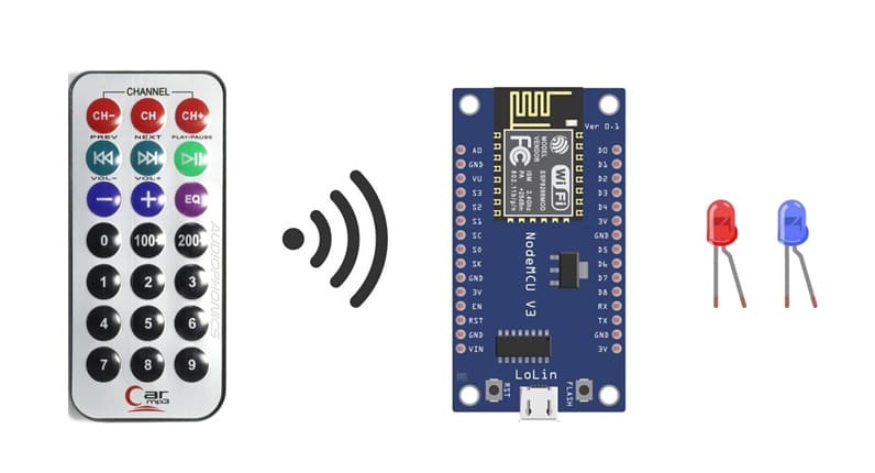
The main objective of this tutorial is to learn how to control two LEDs remotely using an infrared (IR) remote control and an ESP8266 NodeMCU board.
This project demonstrates how to use an IR receiver sensor to capture the signals transmitted by the remote control and how to program the ESP8266 to interpret these signals and control LEDs accordingly.
Through this tutorial, you will:
- understand how infrared communication works between a remote control and an electronic device.
- learn how to connect and interface an IR receiver with the ESP8266 NodeMCU.
- discover how to decode IR signals sent by different buttons on the remote control.
- write a MicroPython program that reads the IR codes and performs actions such as turning LEDs ON or OFF based on the button pressed.
Gain experience in building a simple remote-controlled lighting system, which can later be expanded to control other devices such as motors, relays, or home automation systems.
At the end of this tutorial, you will have a functional system where:
- pressing specific buttons on the remote allows you to turn both LEDs on or off,
- or control each LED individually, showing how an IR remote can easily manage multiple outputs on the ESP8266 board.
The necessary components
ESP8266 NodeMCU Board
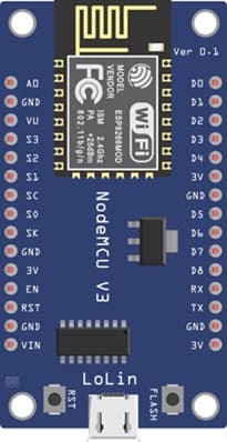
The main microcontroller that receives signals from the IR sensor and controls the LEDs.
IR Receiver Module (KY-032)
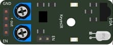
Captures infrared signals from the remote control and sends them to the ESP8266 as digital codes.
IR Remote Control

Sends infrared signals. Each button emits a unique code that the ESP8266 can interpret to control LEDs.
Two LEDs (e.g., red and blue)
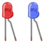
These LEDs will be controlled individually or together by the remote control.
Two 220 Ω Resistors
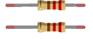
Limit the current flowing through the LEDs to prevent damage.
Breadboard
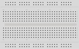
For easy connections of all components without soldering.
Jumper Wires
Used to connect the ESP8266, LEDs, and IR receiver on the breadboard.
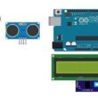
Assembly of the electronic system
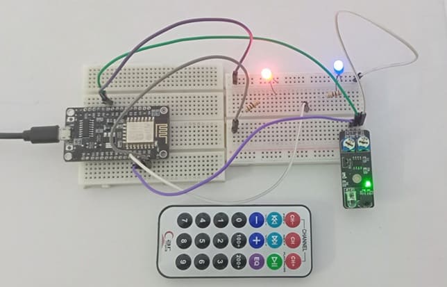
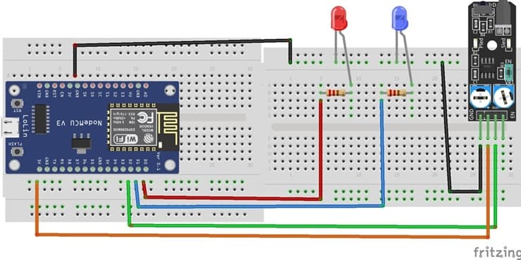
The system consists of an ESP8266 NodeMCU, an IR receiver, an IR remote control, and two LEDs (red and blue). The components are connected on a breadboard using jumper wires.
1. Connecting the IR Receiver
VCC → 3.3V of ESP8266
GND → GND of ESP8266
OUT → D2 (GPIO4) for signal input
2. Connecting the LEDs
Each LED is connected to a digital pin of the ESP8266 through a 220 Ω resistor:
LED 1 (Red):
Anode (+) → D0(GPIO16) via 220 Ω resistor
Cathode (–) → GND
LED 2 (Blue):
Anode (+) → D1 (GPIO5) via 220 Ω resistor
Cathode (–) → GND
Program ESP8266 NodeMCU with MicroPython
You'll need to install the ir_rx library to work with the KY-032 infrared sensor.
|
1 2 3 4 5 6 7 8 9 10 11 12 13 14 15 16 17 18 19 20 21 22 23 24 25 26 27 28 29 30 31 32 33 34 35 36 37 38 39 40 41 42 |
# More details can be found in TechToTinker.blogspot.com # George Bantique | tech.to.tinker@gmail.com from machine import Pin from ir_rx import NEC_16 # define LED pins led_red=Pin(16, Pin.OUT) led_blue=Pin(5, Pin.OUT) # define ky-032 sensor pin ir_gpio=Pin(4, Pin.IN) def ir_callback(data, addr, ctrl): global ir_data global ir_addr if data > 0: ir_data = data ir_addr = addr print('Data {:02x} Addr {:04x}'.format(data, addr)) ir = NEC_16(ir_gpio, ir_callback) ir_data = 0 ir_addr = 0 led_red.value(0) # turn off red LED led_blue.value(0) # turn off blue LED while True: if ir_data > 0: if ir_data==0x0C: # press button 1 on the remote control led_red.value(1) # turn on red LED led_blue.value(1) # turn on blue LED if ir_data==0x18: # press button 2 on the remote control led_red.value(0) # turn off red LED led_blue.value(0) # turn off blue LED if ir_data==0x08: # press button 4 on the remote control led_red.value(1) # turn on red LED led_blue.value(0) # turn off blue LED if ir_data==0x1C: # press button 5 on the remote control led_red.value(0) # turn off red LED led_blue.value(1) # turn on blue LED ir_data = 0 |
Now, when you use the specific buttons on the remote control associated with the mapped IR codes, the two LEDs should turn on and off accordingly.
0 comment
Leave a comment
Passion for robotics

Recent tutorials


Robotics workshop

Polpular tutorials


Making robots

Most commented tutorials


Robotic arm

Categories
Smart Home