DIY Speed Radar Using ESP32 and HC-SR04 Sensor
Tutorial plan
1- Objective of the project
2- Required Components
3- Circuit Connections of system
4- Micropython program of ESP32
Objective of the project
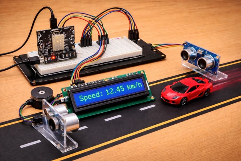
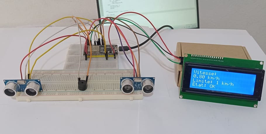
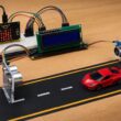
The objective of this project is to design and implement a DIY speed radar system using an ESP32 board, two HC-SR04 ultrasonic sensors, an I2C LCD display, and a buzzer.
The system is designed to measure the speed of a moving object by calculating the time it takes to travel between two fixed points. This project helps demonstrate how embedded systems can be used for real-time measurement and monitoring applications.
It also reinforces concepts such as sensor integration, time measurement, distance-based speed calculation, and human-machine interaction through visual and audio outputs.
Functioning of the Project:
The system works by placing two HC-SR04 ultrasonic sensors at a known fixed distance from each other. When an object passes in front of the first sensor, the ESP32 records the starting time. As the object moves forward and is detected by the second sensor, the ending time is recorded.
The ESP32 then calculates the time difference and uses the distance between the sensors to compute the speed of the object. The calculated speed is displayed on the I2C LCD screen in real time.
If the measured speed exceeds a predefined limit, the buzzer is activated to produce an audible alert, warning that the speed is too high. If the speed is within the acceptable range, a normal status is displayed. The system operates continuously, allowing real-time monitoring of moving objects.
Required Components
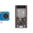
1. ESP32 board
The ESP32 is the main controller of the project. It processes the signals from the sensors, performs the speed calculations, and manages the output devices such as the LCD display and the buzzer.
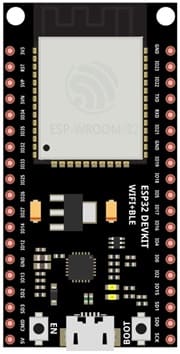
2. HC-SR04 sensor
Two HC-SR04 ultrasonic sensors are used to detect the presence of a moving object at two different points. Each sensor measures distance by emitting ultrasonic waves and receiving the reflected signal. By detecting when an object passes in front of each sensor, the system can calculate the time difference needed to compute speed.
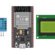
4. LCD Display with I2C Module

The I2C LCD screen is used to display real-time information such as the measured speed, system status, and warning messages.
5. Breadboard

A breadboard is used to assemble the circuit without soldering. It makes it easy to connect and modify the components during testing and development.
6. Jumper Wires

Jumper wires are used to connect the ESP32 board, HC-SR04 sensors, and LCD display together. They ensure proper electrical connections between all components.
Circuit Connections of system
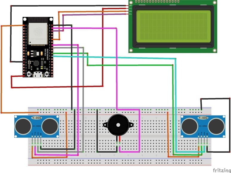
1- Connecting the first HC-SR04 sensor to the ESP32 board
| HC-SR04 | ESP32 board |
|---|---|
| VCC | 3 V |
| Trig | GPIO 19 |
| Echo | GPIO 18 |
| GND | GND |
2- Connecting the second HC-SR04 sensor to the ESP32 board
| HC-SR04 | ESP32 board |
|---|---|
| VCC | 3 V |
| Trig | GPIO 17 |
| Echo | GPIO 16 |
| GND | GND |
3- Connecting the Buzzer to the ESP32 board
| Buzzer | ESP32 board |
|---|---|
| (+) Terminal | GPIO 23 |
| (-) Terminal | GND |
4- Connection of LCD I2C display to ESP32 board
| LCD I2C display | ESP32 board |
|---|---|
| VCC | 5V of GPIO card |
| GND | GND |
| SDA | GPIO 21 |
| SCL | GPIO 22 |
Micropython program of ESP32
This Micropython program implements a DIY speed radar system using an ESP32 microcontroller, two HC-SR04 ultrasonic sensors, an I2C LCD display, and a buzzer. The main purpose of the system is to measure the speed of a moving object by calculating the time it takes to travel between two fixed points.
You need to install this libraries : i2c_lcd et lcd_api for I2C LCD screen
|
1 2 3 4 5 6 7 8 9 10 11 12 13 14 15 16 17 18 19 20 21 22 23 24 25 26 27 28 29 30 31 32 33 34 35 36 37 38 39 40 41 42 43 44 45 46 47 48 49 50 51 52 53 54 55 56 57 58 59 60 61 62 63 64 65 66 67 68 69 70 71 72 73 74 75 76 77 78 79 80 81 82 83 84 85 86 87 88 89 90 91 92 93 94 95 96 97 98 99 100 101 102 103 104 105 106 107 108 109 110 111 112 113 114 115 116 117 118 119 120 121 122 123 124 125 126 127 128 129 130 131 132 133 134 135 136 137 138 139 140 141 142 143 144 145 146 147 148 149 150 151 152 153 154 155 156 157 158 159 160 161 162 163 |
# Import required libraries from machine import Pin, I2C, time_pulse_us import time from i2c_lcd import I2cLcd # ========================= # CONFIGURATION # ========================= # Distance between the two sensors (in meters) DISTANCE = 0.20 # Detection threshold (object detected if distance < this value in cm) SEUIL_DETECTION = 10 # Maximum allowed speed (km/h) LIMITE_VITESSE = 1 # ========================= # SENSOR SETUP # ========================= # Sensor 1 (entry point) trig1 = Pin(19, Pin.OUT) # Trigger pin echo1 = Pin(18, Pin.IN) # Echo pin # Sensor 2 (exit point) trig2 = Pin(17, Pin.OUT) echo2 = Pin(16, Pin.IN) # Buzzer (alarm output) buzzer = Pin(23, Pin.OUT) # ========================= # LCD SETUP (I2C DISPLAY) # ========================= i2c = I2C(0, scl=Pin(22), sda=Pin(21), freq=400000) lcd = I2cLcd(i2c, 0x27, 4, 20) # ========================= # FUNCTIONS # ========================= def mesurer_distance(trig, echo): # Send ultrasonic pulse trig.value(0) time.sleep_us(2) trig.value(1) time.sleep_us(10) trig.value(0) # Measure echo return time duree = time_pulse_us(echo, 1, 30000) # If no echo received, return None if duree < 0: return None # Convert time to distance (cm) return (duree * 0.0343) / 2 def objet_detecte(trig, echo): # Check if an object is detected within threshold distance d = mesurer_distance(trig, echo) return d is not None and d < SEUIL_DETECTION def afficher(l1="", l2="", l3="", l4=""): # Display text on 4-line LCD screen lcd.clear() lcd.move_to(0, 0) lcd.putstr(l1) lcd.move_to(0, 1) lcd.putstr(l2) lcd.move_to(0, 2) lcd.putstr(l3) lcd.move_to(0, 3) lcd.putstr(l4) def bip(duree=200): # Activate buzzer for a given duration (ms) buzzer.value(1) time.sleep_ms(duree) buzzer.value(0) # ========================= # INITIALIZATION MESSAGE # ========================= afficher("SPEED RADAR", "Initializing...", "", "") time.sleep(5) # ========================= # MAIN LOOP # ========================= while True: # Display waiting status afficher("Radar active", "Waiting...", "", "") # Wait until object is detected by sensor 1 while not objet_detecte(trig1, echo1): time.sleep_ms(5) # Record time at sensor 1 detection t1 = time.ticks_us() afficher("Vehicle detected", "Measuring...", "", "") # Wait until object is detected by sensor 2 while not objet_detecte(trig2, echo2): time.sleep_ms(5) # Record time at sensor 2 detection t2 = time.ticks_us() # Calculate time difference (in seconds) delta_t = time.ticks_diff(t2, t1) / 1_000_000 # Ensure valid time measurement if delta_t > 0: # Calculate speed in km/h vitesse = (DISTANCE / delta_t) * 3.6 # Display speed and status afficher( "Speed:", "{:.2f} km/h".format(vitesse), "Limit: {} km/h".format(LIMITE_VITESSE), "Status:" ) # ========================= # ALARM MANAGEMENT # ========================= if vitesse > LIMITE_VITESSE: # Overspeed detected lcd.move_to(8, 3) lcd.putstr("OVER") # Continuous warning beep for _ in range(15): bip(150) time.sleep_ms(100) else: # Normal speed lcd.move_to(8, 3) lcd.putstr("OK") bip(80) else: # Error handling afficher("Error", "Invalid time", "", "") # Pause before next measurement cycle time.sleep(5) |
At the beginning, the program initializes all components, including the ultrasonic sensors, LCD screen, and buzzer. It then enters an infinite loop where it continuously monitors for the presence of an object. When an object is detected by the first ultrasonic sensor, the system records the starting time. As the object continues moving and is detected by the second sensor, the ending time is recorded.
The ESP32 then calculates the time difference between the two detections and uses the known distance between the sensors to compute the object’s speed in km/h. This speed value is displayed in real time on the LCD screen along with a status message.
If the measured speed exceeds a predefined limit, the buzzer is activated to produce a warning sound, indicating an overspeed condition. If the speed is within the allowed limit, a normal status message is shown. The system repeats this process continuously, allowing real-time speed monitoring of passing objects.
0 comment
Leave a comment
Passion for robotics

Recent tutorials

Robotics workshop

Polpular tutorials


Making robots

Most commented tutorials


Robotic arm

Categories
Smart Home