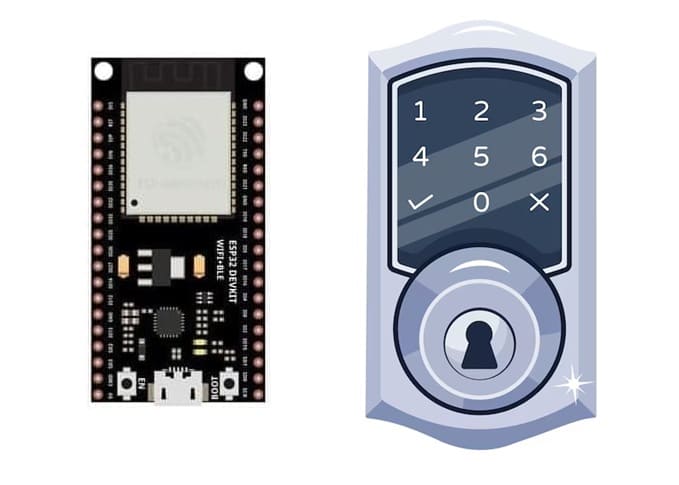
Door opening controlled by ESP32 and 4×3 matrix keypad
Tutorial plan
1- Secure access system using digital keypad
2- How open a door using ESP32 board and 4x3 matrix keypad ?
3- Required Components
4- Circuit Connections of system
5- Micropython program of system
Secure access system using digital keypad
A Secure Access System using a Digital Keypad is an electronic security mechanism designed to restrict entry to authorized individuals by requiring them to input a specific code through a digital keypad. This system is commonly used in homes, offices, laboratories, and other restricted areas. Below is a detailed description of such a system from a general perspective:
The Secure Access System using Digital Keypad is an authentication-based system where access is granted only if the correct passcode is entered on the keypad. The system typically involves a microcontroller (like Arduino, ESP32, or Micro:bit), a keypad (usually 4x4 or 4x3), a display (LCD/OLED), and an actuator (such as a servo motor, magnetic lock, or relay) to physically unlock the door or gate.
Working Principle
1- Initialization
System boots up and displays a prompt (e.g., “Enter Password”).
2- Code Entry
User enters a pre-set code using the keypad.
Each keypress is registered by the microcontroller and optionally displayed as * for security.
3- Code Verification
The entered code is compared with a stored password.
The password can be hard-coded or stored in EEPROM or an external memory module.
4- Access Decision
- If the code matches:
The actuator (e.g., servo motor) is triggered to unlock the door.
A message like “Access Granted” is shown.
- If the code is incorrect:
A warning is shown (e.g., “Access Denied”), and optionally a buzzer sounds.
5- Security Features (optional)
- Limited number of attempts before lockout.
- Delay between failed attempts.
- Alarm trigger after several wrong entries.
- Logging access attempts to memory or cloud.
Advantages
- Simple and effective: Easy to implement and use.
- No keys needed: Eliminates the need for physical keys.
- Customizable: Codes can be changed easily without replacing hardware.
- Secure: With proper safeguards like limited attempts, it offers decent protection.
How open a door using ESP32 board and 4x3 matrix keypad ?
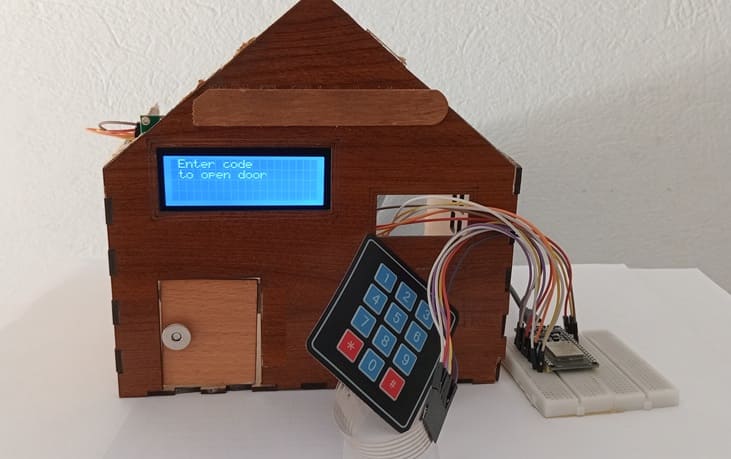
To design a secure electronic door lock system that allows access only when the correct password is entered through a 4x3 matrix keypad. The ESP32 microcontroller processes the input, and if the password is correct, it activates a servo motor to unlock the door. A 16x2 I2C LCD display provides real-time feedback to the user.
Working Principle
1- Startup:
- The system initializes all components.
- The LCD displays: “Enter Password”.
2- User Input:
- User enters a numeric password using the keypad.
- The LCD displays * for each digit to hide the input.
3- Password Verification:
- After entering the password and pressing a specific key (e.g., #), the ESP32 compares the input with the stored password.
4- Door Control:
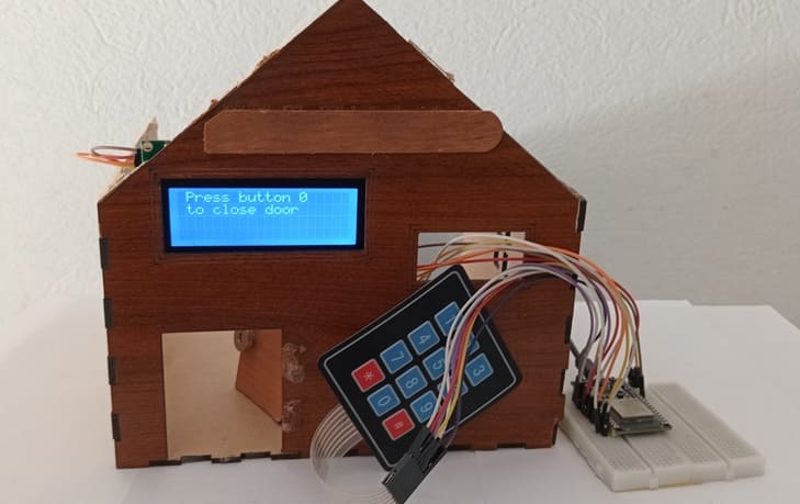
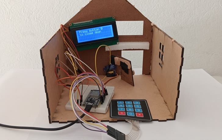
- Correct password: The servo motor rotates to unlock position (e.g., 90°), LCD shows “Access Granted”, then after a few seconds returns to locked position (0°).
- Wrong password: LCD displays “Access Denied”, and servo remains locked.
Required Components
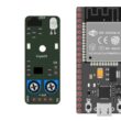
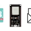
1. ESP32 Development Board
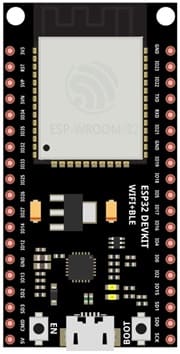
Function: Acts as the brain of the system. It processes keypad inputs, controls the servo motor, and communicates with the LCD.
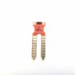
2. 4x3 Matrix Keypad
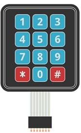
Function: Used by the user to enter a numeric password.
Working: When a key is pressed, it connects a specific row and column, which the ESP32 detects via GPIO scanning.
3. LCD Display (with I2C Module)
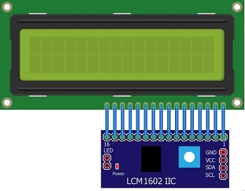
Function: Displays messages like "Enter Password", "Access Granted", or "Access Denied".
4. SG90 Servo Motor
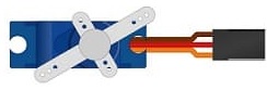
Function: Acts as the physical door lock actuator. Rotates to unlock and lock the door.
5. Breadboard

Breadboard is used for building a non-permanent circuit without soldering.
6. Jumper Wires

Jumper wires (male-to-male or male-to-female) are used to connect components to the Micro:bit.
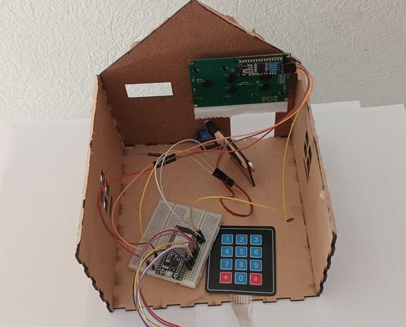
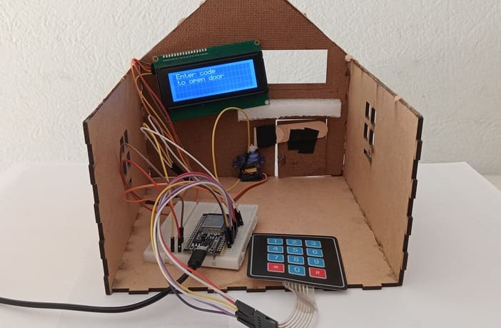
7. Wooden house prototype
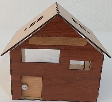
A miniature wooden house represents a real-world structure.
The door mechanism is attached to a servo motor, which rotates to open or close it.
The wooden prototype provides a stable frame for installing components like the IR sensor and LCD screen.
Circuit Connections of system
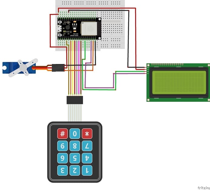
Connection of I2C LCD display
LCD I2C Pin | ESP32 pin |
VCC | 5 volt |
GND | GND |
SDA | GPIO 21 |
SCL | GPIO 22 |
Connection of servo motor
Servo motor | ESP32 |
Brown wire (-) | GND |
Red wire (+) | 5V |
Yellow wire (Signal) | GPIO 23 |
Connection of matrix keypad
4x3 Matrix Keypad | ESP32 board |
Pin 1 (located on the left) | GPIO 19 |
Pin 2 | GPIO 18 |
Pin 3 | GPIO 5 |
Pin 4 | GPIO 17 |
Pin 5 | GPIO 16 |
Pin 6 | GPIO 4 |
Pin 7 | GPIO 2 |
Micropython program of system
Before running the code, install the necessary libraries:
- DIYables_MicroPython_Keypad (for matrix keypad)
- i2c_lcd and lcd_api (for I2C LCD screen)
- Servo (for servo motor)
|
1 2 3 4 5 6 7 8 9 10 11 12 13 14 15 16 17 18 19 20 21 22 23 24 25 26 27 28 29 30 31 32 33 34 35 36 37 38 39 40 41 42 43 44 45 46 47 48 49 50 51 52 53 54 55 56 57 58 59 60 61 62 63 64 65 66 67 68 69 70 71 72 73 74 75 76 77 78 79 80 81 82 83 84 85 86 87 88 89 90 91 92 93 94 95 96 97 98 99 100 101 102 103 104 105 106 107 108 109 110 111 112 113 114 115 116 117 118 119 120 121 122 123 124 |
# Include necessary libraries import machine from machine import Pin, SoftI2C from time import sleep from servo import Servo from lcd_api import LcdApi from i2c_lcd import I2cLcd from ir_rx import NEC_16 from DIYables_MicroPython_Keypad import Keypad # Initialize LCD at I2C address 0x27 with 20 columns and 4 rows I2C_ADDR = 0x27 totalRows = 4 totalColumns = 20 i2c = SoftI2C(scl=Pin(22), sda=Pin(21), freq=10000) #initializing the I2C method for ESP32 lcd = I2cLcd(i2c, I2C_ADDR, totalRows, totalColumns) UM_ROWS = 4 NUM_COLS = 3 # Constants for GPIO pins ROW_PINS = [19, 18, 5, 17] # The ESP32 pin GPIO18, GPIO5, GPIO17, GPIO16 connect to the row pins COLUMN_PINS = [16, 4, 2] # The ESP32 pin GPIO4, GPIO0, GPIO2 connect to the column pins # Keymap corresponds to the layout of the keypad 3x4 KEYMAP = ['1', '2', '3', '4', '5', '6', '7', '8', '9', '*', '0', '#'] # Initialize the keypad keypad = Keypad(KEYMAP, ROW_PINS, COLUMN_PINS, NUM_ROWS, NUM_COLS) keypad.set_debounce_time(400) # 400ms, addjust it if it detects twice for single press #Create servo object motor=Servo(pin=23) motor.move(90) # turn the servo votor to close the door lcd.clear() lcd.move_to(1,0) lcd.putstr("Enter code") lcd.move_to(1,1) lcd.putstr("to open door") # variables system code="" etoiles="" position_door=90 while True: key = keypad.get_key() if key : #If a key is pressed if key!="#": code=code+key etoiles=etoiles+"*" lcd.move_to(1,2) lcd.putstr(etoiles) # Show stars on the LCD display else: # if we presse the # button if code=="1234" and position_door==90 : # if code is valid lcd.clear() lcd.move_to(1,0) lcd.putstr("Valide code") lcd.move_to(1,1) lcd.putstr("Door opens") for i in range(91,19,-1): motor.move(i) # Move servo to open the door sleep(0.1) position_door=20 lcd.clear() lcd.move_to(1,1) lcd.putstr("Door open") sleep(5) lcd.clear lcd.move_to(1,0) lcd.putstr("Press button 0") lcd.move_to(1,1) lcd.putstr("to close door") code="" etoiles="" position_door=20 else: if code=="0" and position_door==20 : # we press the button 0 lcd.clear() lcd.move_to(1,1) lcd.putstr("Door closes") for i in range(20,91): motor.move(i) # turn the servo to close the door sleep(0.1) position_door=90 lcd.clear() lcd.move_to(1,1) lcd.putstr("Door closed") sleep(5) lcd.clear() lcd.move_to(1,0) lcd.putstr("Enter code") lcd.move_to(1,1) lcd.putstr("to open door") code="" etoiles="" position_door=90 else : # if the code is invalid lcd.clear() lcd.move_to(1,0) lcd.putstr("Invalid code") lcd.move_to(1,1) lcd.putstr("Access denied") sleep(5) lcd.clear() lcd.move_to(1,0) lcd.putstr("Enter code") lcd.move_to(1,1) lcd.putstr("to open door") code="" etoiles="" |
0 comment
Leave a comment
Passion for robotics

Recent tutorials


Robotics workshop

Polpular tutorials


Making robots

Most commented tutorials


Robotic arm

Categories
Smart Home