ESP32 Alarm Clock with DS1302 RTC Module
Tutorial plan
1- Objective of the project
2- Required Components
3- Circuit Connections of system
4- Micropython program of ESP32 Alarm Clock
Objective of the project
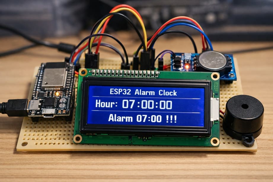
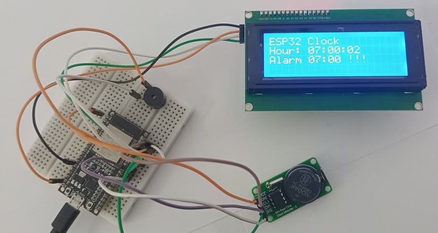
The objective of this project is to design and implement a digital alarm clock system using an ESP32 microcontroller, a DS1302 Real-Time Clock (RTC) module, an I2C LCD display, and a buzzer. The system is capable of displaying the current time in real time and activating an audible alarm at a predefined time, such as 07:00:00. This project demonstrates how to integrate timekeeping hardware with a microcontroller to create a practical and interactive embedded system.
Functioning of the System
The system operates by using the DS1302 RTC module to keep track of the current time continuously, even when the ESP32 is powered off, thanks to its backup battery. The ESP32 communicates with the RTC module to read the current hour, minute, and second.
The ESP32 then sends this time information to the LCD I2C display, which shows the current time in a clear format, such as: Hour: 07:00:00
The ESP32 constantly compares the current time from the RTC module with the preset alarm time (07:00:00). When the current time matches the alarm time, the ESP32 activates the buzzer to produce a sound and displays an alarm message on the LCD screen: Alarm 07:00 !!!
The buzzer turns on and off repeatedly to create an audible alert, while the message remains visible on the LCD to inform the user that the alarm has been triggered.
After the alarm duration is completed, the buzzer stops, and the system continues to operate normally, displaying the current time and waiting for the next alarm condition.
Required Components
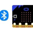
1. BBC Micro:bit (Microcontroller)
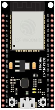
The ESP32 is the main controller of the system. It reads the current time from the DS1302 RTC module, processes the alarm condition, updates the LCD display, and controls the buzzer.
2. DS1302 RTC Module
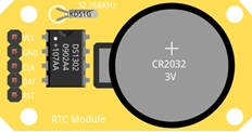
The DS1302 is a Real-Time Clock (RTC) module used to keep track of the current time and date. It can maintain accurate time even when the ESP32 is powered off because it uses a backup battery. It provides information such as year, month, day, hour, minute, and second. The ESP32 reads this data through digital communication pins.
3. Buzzer
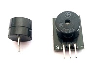
The buzzer is an electronic sound device that produces sound when activated by the ESP32. It is used to alert the user when the alarm time is reached.
4. LCD Display with I2C Module

The LCD display is used to show the current time and alarm messages.
5. Breadboard

A breadboard is used to build the circuit without soldering.
6. Jumper Wires

Jumper wires are used to connect the ESP32 to the RTC module, the LCD display and the Buzzer. They allow electrical signals and power to flow between the components.
Circuit Connections of system
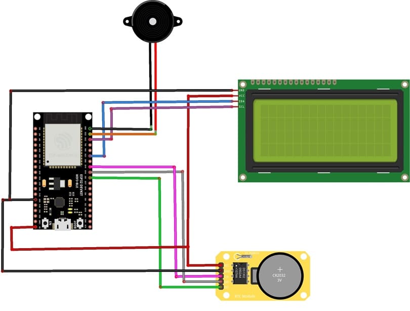
1- Connection of DS1302 RTC Module to ESP32
| DS1302 RTC | ESP32 board |
|---|---|
| CLK | GPIO 19 |
| DAT | GPIO 18 |
| RST | GPIO 5 |
| VCC | 5V |
| GND | GND |
2- Connection of LCD I2C display to ESP32
| LCD display | ESP32 board |
|---|---|
| VCC | 5V |
| GND | GND |
| SDA | GPIO 21 |
| SCL | GPIO 22 |
3- Connection of Buzzer to ESP32
| Buzzer | ESP32 board |
|---|---|
| Pin (+) | GPIO 23 |
| Pin (-) | GND |
Micropython program of ESP32 Alarm Clock
This MicroPython program implements a digital alarm clock system using an ESP32 microcontroller, a DS1302 Real-Time Clock (RTC) module, an I2C LCD display, and a buzzer.
The purpose of the program is to display the current time continuously and activate an audible alarm when a predefined time is reached.
You need to install this libraries :
i2c_lcd et lcd_api for I2C LCD screen
ds1302 for DS1302 RTC module
|
1 2 3 4 5 6 7 8 9 10 11 12 13 14 15 16 17 18 19 20 21 22 23 24 25 26 27 28 29 30 31 32 33 34 35 36 37 38 39 40 41 42 43 44 45 46 47 48 49 50 51 52 53 54 55 56 57 58 59 60 61 62 63 64 65 66 67 68 69 70 71 72 73 74 75 76 77 78 79 80 81 82 83 84 85 86 87 88 89 90 91 92 93 94 95 96 97 98 99 100 101 102 103 104 105 106 107 108 109 110 111 112 113 114 115 116 117 118 119 120 121 122 123 124 125 126 127 128 129 130 131 132 133 134 135 136 |
# Import the Pin class to control GPIO pins # and the I2C class for communication with the LCD display from machine import Pin, I2C # Import the library to control the I2C LCD display from i2c_lcd import I2cLcd # Import the DS1302 RTC (Real Time Clock) module library import ds1302 # Import the time library for delays import time # ================= LCD I2C CONFIGURATION ================= # I2C address of the LCD display (commonly 0x27 or 0x3F) I2C_ADDR = 0x27 # Initialize the LCD: # I2C(0) → I2C bus number 0 # scl=Pin(22) → GPIO22 used as I2C clock line # sda=Pin(21) → GPIO21 used as I2C data line # 4, 20 → LCD with 4 rows and 20 columns lcd = I2cLcd(I2C(0, scl=Pin(22), sda=Pin(21)), I2C_ADDR, 4, 20) # Clear the LCD screen lcd.clear() # ================= DS1302 RTC MODULE CONFIGURATION ================= # Define the GPIO pins connected to the RTC module clk = Pin(19) # CLK pin (clock signal) dat = Pin(18) # DAT pin (data line) rst = Pin(5) # RST pin (reset) # Create the RTC object rtc = ds1302.DS1302(clk, dat, rst) # ⚠️ IMPORTANT: # This line sets the date and time of the RTC module. # Execute it ONLY ONCE, then comment it to avoid resetting # the time every time the ESP32 restarts. rtc.date_time([2026, 2, 6, 5, 6, 59, 55]) # Format: # [year, month, day, weekday, hour, minute, second] # ================= BUZZER CONFIGURATION ================= # Set GPIO23 as an output to control the buzzer buzzer = Pin(23, Pin.OUT) # buzzer.value(0) → buzzer OFF # buzzer.value(1) → buzzer ON # ================= MAIN PROGRAM ================= # Infinite loop while True: # Read the current date and time from the RTC module t = rtc.date_time() # The list t contains: # t[0] = year # t[1] = month # t[2] = day # t[3] = weekday # t[4] = hour # t[5] = minute # t[6] = second # Display the title on the first line lcd.move_to(0, 0) lcd.putstr("ESP32 Clock") # Display the time on the second line lcd.move_to(0, 1) # {:02d} formats numbers with two digits (e.g., 07 instead of 7) lcd.putstr("Hour: {:02d}:{:02d}:{:02d}".format(t[4], t[5], t[6])) # ================= ALARM CHECK ================= # If the time is exactly 07:00:00 if (t[4] == 7) and (t[5] == 0) and (t[6] == 0): lcd.move_to(0, 1) # Repeat the alarm 10 times for i in range(10): # Read the current time again t = rtc.date_time() # Display the updated time lcd.move_to(0, 1) lcd.putstr("Hour: {:02d}:{:02d}:{:02d}".format(t[4], t[5], t[6])) # Display the alarm message lcd.move_to(0, 2) lcd.putstr('Alarm 07:00 !!!') # Turn the buzzer ON buzzer.value(1) # Wait for 1 second time.sleep(1) # Read the time again t = rtc.date_time() # Display the updated time lcd.move_to(0, 1) lcd.putstr("Hour: {:02d}:{:02d}:{:02d}".format(t[4], t[5], t[6])) # Clear the alarm message lcd.move_to(0, 2) lcd.putstr(' ') # Turn the buzzer OFF buzzer.value(0) # Wait for 1 second time.sleep(1) # Optional short delay to stabilize display updates # time.sleep(0.5) |
1 comment

best site to buy viagra online 03-04-2626
View explicit videos securely on reputable adult platforms. Find reliable video sources for a premium experience.
Leave a comment
Passion for robotics

Recent tutorials


Robotics workshop

Polpular tutorials


Making robots

Most commented tutorials


Robotic arm

Categories
Smart Home