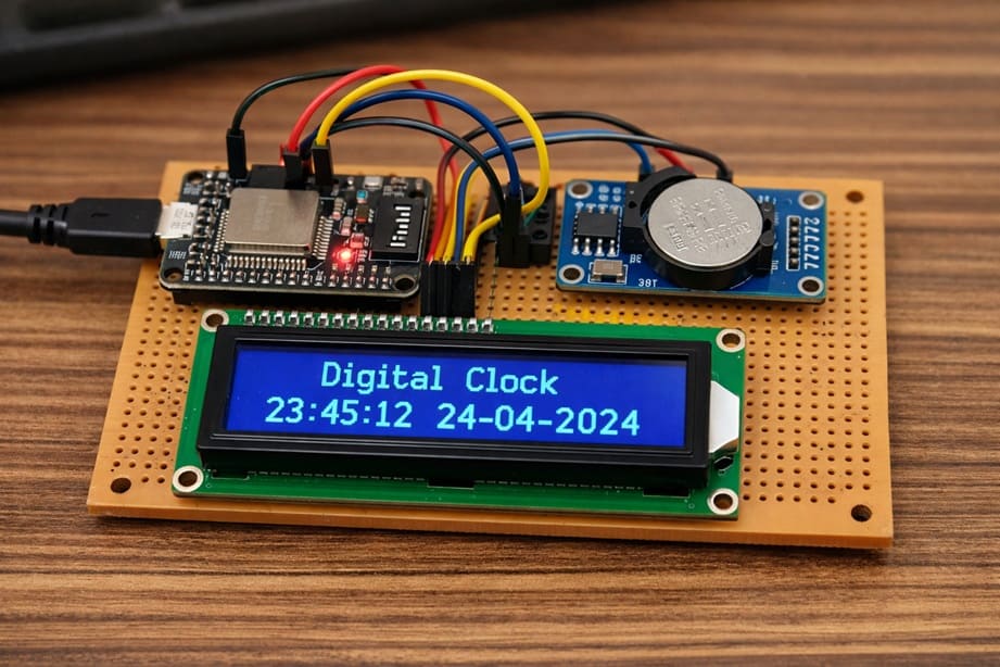
ESP32 digital Clock with DS1302 RTC module
Tutorial plan
1- Objective of the project
2- Required Components
3- Circuit Connections of system
4- Micropython program of ESP32 Clock
Objective of the project
The objective of this project is to design and build a digital clock using the ESP32 microcontroller, a DS1302 RTC Module, and an LCD I2C display to show the current date and time in real time.
This project aims to:
- learn how to interface the ESP32 with a DS1302 RTC Module to read accurate time and date information
- display the current time (hours, minutes, and seconds) and date on an LCD I2C screen
- understand how real-time clock (RTC) modules maintain time even when the main power is turned off using a backup battery
- practice using the I2C communication protocol to control the LCD display
- develop skills in MicroPython programming for embedded systems
- build a complete and practical embedded system project
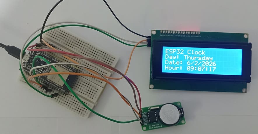
At the end of this project, the ESP32 will continuously read the current time from the RTC module and display it clearly on the LCD I2C screen, creating a functional and reliable digital clock.
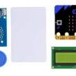
Required Components
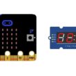
1. BBC Micro:bit (Microcontroller)
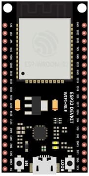
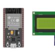
The ESP32 is the main microcontroller of the project. It controls all connected components and executes the MicroPython program.
2. DS1302 RTC Module
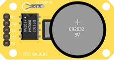
The DS1302 is a Real-Time Clock (RTC) module used to keep track of the current time and date. It can maintain accurate time even when the ESP32 is powered off because it uses a backup battery. It provides information such as year, month, day, hour, minute, and second. The ESP32 reads this data through digital communication pins.
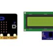
3. LCD Display with I2C Module

The LCD I2C display is used to show the date and time to the user. It uses the I2C communication protocol, which requires only two wires (SDA and SCL), making connections simpler. The display can show text such as the day, date, and current time in real time.
4. Breadboard

A breadboard is used to build the circuit without soldering.
5. Jumper Wires

Jumper wires are used to connect the ESP32 to the RTC module and the LCD display. They allow electrical signals and power to flow between the components.
Circuit Connections of system
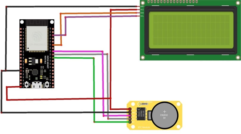
1- Connection of DS1302 RTC Module to ESP32
| DS1302 RTC | ESP32 board |
|---|---|
| CLK | GPIO 19 |
| DAT | GPIO 18 |
| RST | GPIO 5 |
| VCC | 5V |
| GND | GND |
2- Connection of LCD I2C display to ESP32
| LCD display | ESP32 board |
|---|---|
| VCC | 5V |
| GND | GND |
| SDA | GPIO 21 |
| SCL | GPIO 22 |
Micropython program of ESP32 Clock
This program is designed to create a digital clock system using the ESP32, a DS1302 RTC Module, and an LCD I2C Display 20x4. It reads the current date and time from the RTC module and displays them on the LCD screen in real time.
You need to install this libraries :
i2c_lcd et lcd_api for I2C LCD screen
ds1302 for DS1302 RTC module
|
1 2 3 4 5 6 7 8 9 10 11 12 13 14 15 16 17 18 19 20 21 22 23 24 25 26 27 28 29 30 31 32 33 34 35 36 37 38 39 40 41 42 43 44 45 46 47 48 49 50 51 52 53 54 55 56 57 58 59 60 61 62 63 64 65 66 67 68 69 70 71 72 73 74 75 76 77 78 79 80 81 82 83 84 85 86 87 88 89 90 91 92 93 94 95 96 97 98 99 100 101 102 103 104 105 |
# Import the Pin class to control GPIO pins # and the I2C class for I2C communication from machine import Pin, I2C # Import the library to control the I2C LCD display from i2c_lcd import I2cLcd # Import the DS1302 RTC module library import ds1302 # Import the time library (useful for delays) import time # ================= LCD I2C DISPLAY CONFIGURATION ================= # Define the I2C address of the LCD display (commonly 0x27 or 0x3F) I2C_ADDR = 0x27 # Initialize I2C communication # I2C(0) : use I2C bus number 0 # scl=Pin(22) : GPIO22 connected to SCL pin of LCD # sda=Pin(21) : GPIO21 connected to SDA pin of LCD # 4 : number of LCD rows # 20 : number of LCD columns lcd = I2cLcd(I2C(0, scl=Pin(22), sda=Pin(21)), I2C_ADDR, 4, 20) # Clear the LCD screen lcd.clear() # ================= DS1302 RTC MODULE CONFIGURATION ================= # Define the GPIO pins connected to the RTC module clk = Pin(19) # CLK pin (clock signal) dat = Pin(18) # DAT pin (data signal) rst = Pin(5) # RST pin (reset signal) # Create an rtc object to control the DS1302 module rtc = ds1302.DS1302(clk, dat, rst) # ================= SET DATE AND TIME ================= # ⚠️ This instruction must be executed ONLY ONCE and then commented # It sets the date and time inside the RTC module rtc.date_time([2026, 2, 6, 5, 9, 6, 0]) # Format: # [year, month, day, weekday, hour, minute, second] # ================= FUNCTION TO CONVERT DAY NUMBER TO TEXT ================= def get_day(d): # This function converts the weekday number into the weekday name if d == 1: return "Monday" if d == 2: return "Tuesday" if d == 3: return "Wednesday" if d == 4: return "Thursday" if d == 5: return "Friday" if d == 6: return "Saturday" if d == 7: return "Sunday" # ================= MAIN LOOP ================= while True: # Read the current date and time from the RTC module t = rtc.date_time() # Move cursor to column 0, row 0 lcd.move_to(0, 0) # Display the project title lcd.putstr("ESP32 Clock") # Move cursor to column 0, row 1 lcd.move_to(0, 1) # Display the weekday name lcd.putstr("Day: " + get_day(t[3])) # Move cursor to column 0, row 2 lcd.move_to(0, 2) # Display the date in day/month/year format lcd.putstr("Date: {}/{}/{}".format(t[2], t[1], t[0])) # Move cursor to column 0, row 3 lcd.move_to(0, 3) # Display the time in hour:minute:second format # {:02d} ensures two digits (example: 09 instead of 9) lcd.putstr("Hour: {:02d}:{:02d}:{:02d}".format(t[4], t[5], t[6])) |
0 comment
Leave a comment
Passion for robotics

Recent tutorials


Robotics workshop

Polpular tutorials


Making robots

Most commented tutorials


Robotic arm

Categories
Smart Home