Remote-Controlled Door System with ESP32
Tutorial plan
1- Remotely control the opening of a door
2- Remotely Controlling the door with ESP32
3- Required Components
4- Circuit Connections of system
5- Micropython program to control the system
Remotely control the opening of a door
Remotely controlling the opening of a door using a remote control refers to the ability to unlock or open a door wirelessly using a handheld transmitter device. The remote sends signals to a receiver connected to a door-opening mechanism, such as a servo motor, solenoid lock, or relay-controlled motor.
This system is widely used in home automation, garage doors, electronic gates, smart locks, and secure access control systems.
To implement a remote-controlled door-opening system, the following components are required:
1- Remote Control (Transmitter)
Sends a signal when a button is pressed.
Can use infrared (IR), radio frequency (RF), Bluetooth, Wi-Fi, or Zigbee.
Example: Car key fob, TV remote, RF keychain remote.
2- Receiver Module
Installed near the door.
Receives the signal from the remote and processes it.
Example: IR receiver module (VS1838B), RF receiver (433MHz MX-05V), Bluetooth module (HC-05), Wi-Fi module (ESP32/ESP8266).
3- Microcontroller (if needed for processing signals)
Processes the received signal and activates the motor or lock.
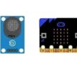
Example: Arduino, ESP32, ESP8266, Micro:bit.
4- Door Opening Mechanism
Servo Motor – Rotates a latch or handle.
Electromagnetic Lock (Solenoid) – Unlocks the door.
Relay-Controlled Motor – Drives an electric motor to open the door.
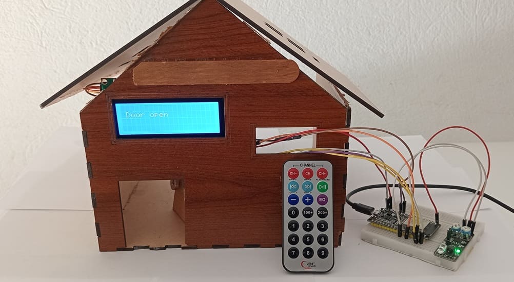
Remotely Controlling the door with ESP32
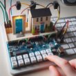
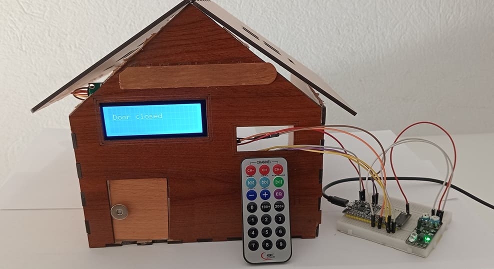
This project showcases a smart door control system that allows users to remotely open and close a door using an infrared (IR) remote control. The system is built using an ESP32 microcontroller, which serves as the brain of the operation, coordinating inputs from the KY-032 IR sensor module (used here to detect IR signals from a remote) and controlling a servo motor to physically open or close the door.
An I2C LCD screen is included in the system to provide real-time visual feedback, such as displaying the current state of the door (e.g., "Door Open", "Door Closed", or "Waiting for Command"), as well as any error messages or confirmation prompts.
How It Works ?
1. System Initialization:
The ESP32 initializes all components.
The LCD displays a welcome message like "Remote Door Control Ready..."
2. Listening for IR Remote Commands:
The KY-032 IR sensor continuously listens for incoming IR signals from the remote.
When a valid signal is received (e.g., a specific button press), the ESP32 decodes it using an IR decoding library.
3. Command Processing:
If the command corresponds to "Open Door", the ESP32 sends a PWM signal to rotate the servo motor, opening the door.
If the command is "Close Door", it rotates the servo in the opposite direction to close the door.
Invalid or unrecognized signals are ignored or flagged with a message on the LCD.
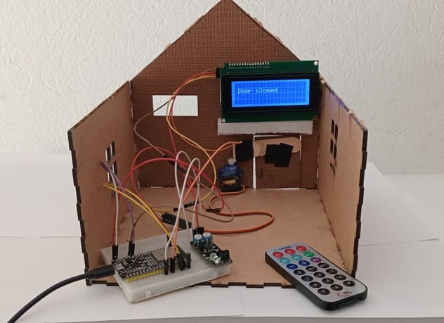
4. Status Display:
The LCD I2C screen updates the status in real-time, showing messages like: "Opening Door" or "Door Closed"
Required Components
ESP32 card
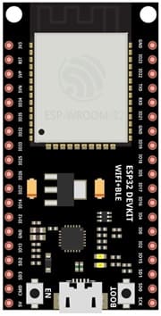
THE ESP32 card is the main controller, offering Wi-Fi and Bluetooth, but used here primarily for GPIO and control logic.
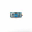
KY-032 IR Sensor
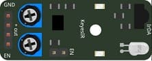
The KY-032 is repurposed to act as an IR receiver that detects signals from an IR remote control.
IR Remote Control

The IR Remote Control sends encoded signals (e.g., NEC protocol) to the sensor, which are interpreted by the ESP32.
Servo Motor (e.g., SG90)

The Servo Motor moves the door open or closed based on remote commands.
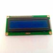
LCD Display (16x2 or 20x4 with I2C module)
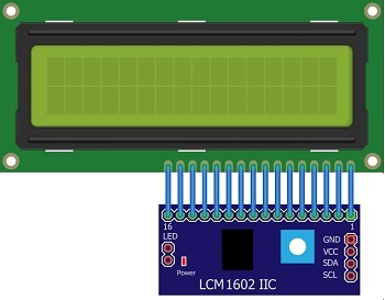
The LCD display shows the system status and messages.
6. Jumper wires
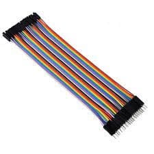
The Jumper wires connect components on a breadboard or directly to the ESP32.
7. Breadboard

The breadboard allows prototyping and easy connection of components without soldering.
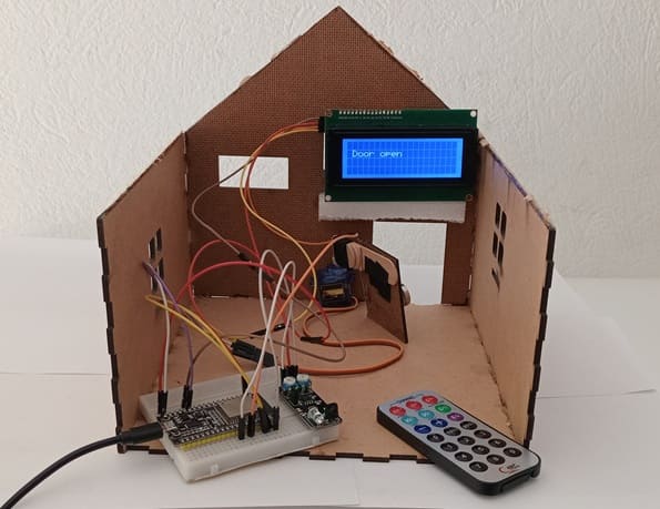
8. Wooden house prototype
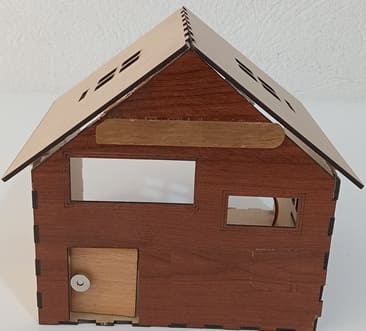
A miniature wooden house represents a real-world structure.
The door mechanism is attached to a servo motor, which rotates to open or close it.
The wooden prototype provides a stable frame for installing components like the IR sensor and LCD screen.
Circuit Connections of system
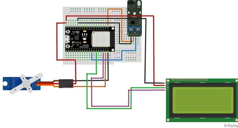
Connection of I2C LCD display
LCD I2C Pin | ESP32 pin |
VCC | 5 volt |
GND | GND |
SDA | GPIO 21 |
SCL | GPIO 22 |
Connection of servo motor
Servo motor | ESP32 |
Brown wire (-) | GND |
Red wire (+) | 5V |
Yellow wire (Signal) | GPIO 23 |
Connection of KY-032 sensor
KY-032 | ESP32 |
GND | GND |
(+) | 3.3V |
OUT | GPIO19 |
Micropython program to control the system
Before running the code, install the necessary libraries:
- Servo (for servo motor)
- i2c_lcd and lcd_api for I2C LCD screen
- ir_rx → for KY-032 sensor
|
1 2 3 4 5 6 7 8 9 10 11 12 13 14 15 16 17 18 19 20 21 22 23 24 25 26 27 28 29 30 31 32 33 34 35 36 37 38 39 40 41 42 43 44 45 46 47 48 49 50 51 52 53 54 55 56 57 58 59 60 61 62 63 64 65 66 67 68 69 70 |
import machine from machine import Pin, SoftI2C from time import sleep from servo import Servo from lcd_api import LcdApi from i2c_lcd import I2cLcd from ir_rx import NEC_16 I2C_ADDR = 0x27 totalRows = 4 totalColumns = 20 # ==== LCD Setup ==== i2c = SoftI2C(scl=Pin(22), sda=Pin(21), freq=10000) #initializing the I2C method for ESP32 lcd = I2cLcd(i2c, I2C_ADDR, totalRows, totalColumns) def ir_callback(data, addr, ctrl): global ir_data global ir_addr if data > 0: ir_data = data ir_addr = addr print('Data {:02x} Addr {:04x}'.format(data, addr)) # ==== KY-032 IR Sensor Setup ==== ir_gpio=Pin(19, Pin.IN) ir = NEC_16(ir_gpio, ir_callback) ir_data = 0 ir_addr = 0 # ==== Servo Setup ==== motor=Servo(pin=23) motor.move(90) # rotate servo to 90° in order to close door position_door=90 lcd.clear() lcd.move_to(1,1) lcd.putstr("Door closed") # print "Door closed" on LCD display while True: if ir_data > 0: #IR Signal Detection if ir_data==0x0C: # we press the button 1 if position_door==90: lcd.clear() lcd.move_to(1,1) lcd.putstr("The door opens") for i in range(91,19,-1): motor.move(i) # rotate servo to 20° in order to open door sleep(0.1) position_door=20 lcd.clear() lcd.move_to(1,1) lcd.putstr("Door open") if ir_data==0x18: # we press the button 2 if position_door==20: lcd.clear() lcd.move_to(1,1) lcd.putstr("The door closes") for i in range(20,91): motor.move(i) # rotate servo to 90° in order to close door sleep(0.1) position_door=90 lcd.clear() lcd.move_to(1,1) lcd.putstr("Door closed") |
0 comment
Leave a comment
Passion for robotics

Recent tutorials


Robotics workshop

Polpular tutorials


Making robots

Most commented tutorials


Robotic arm

Categories
Smart Home