Control RGB LED Module Using ESP8266 NodeMCU Board
Tutorial plan
1- Objective of the tutorial
2- The components needed to control RGB LED module
3- Mounting ESP8266 NodeMCU card with RGB LED module
4- Program ESP8266 NodeMCU with MicroPython
Objective of the tutorial
The main objective of this tutorial is to demonstrate how to use the ESP8266 NodeMCU board to control an RGB LED module by varying the intensity of its three color components: red, green, and blue.
Through this project, you will learn how to connect the RGB LED module to the NodeMCU, configure the GPIO pins for PWM (Pulse Width Modulation) control, and write a MicroPython program that changes the LED colors automatically or based on user input.
This tutorial aims to help you:
- understand the working principle of RGB LEDs and how color mixing is achieved using red, green, and blue light.
- learn how to generate different colors by adjusting PWM duty cycles for each color channel.
- gain practical experience in wiring and programming an RGB LED with the ESP8266 NodeMCU board.
- explore how to create visual effects such as color transitions, blinking patterns, and fading effects.
The components needed to control RGB LED module
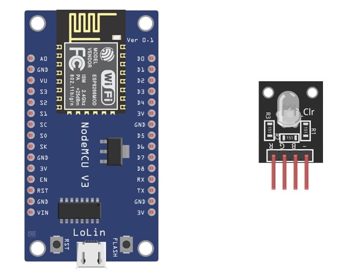
ESP8266 NodeMCU Board
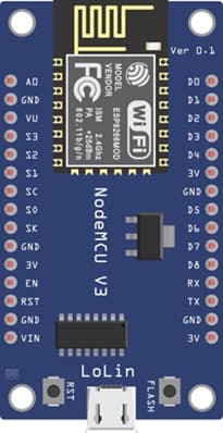
The ESP8266 NodeMCU Board is the main microcontroller. It is used to generate PWM signals and control the RGB LED module.
RGB LED Module
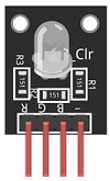
The LED component that produces red, green, and blue colors by combining three internal LEDs.
Breadboard
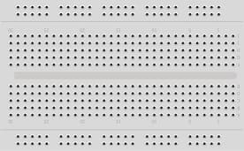
It is used to easily connect the components without soldering.
Jumper Wires
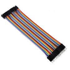
We use the jumper wires to connect the RGB LED module to the NodeMCU pins.
Mounting ESP8266 NodeMCU card with RGB LED module
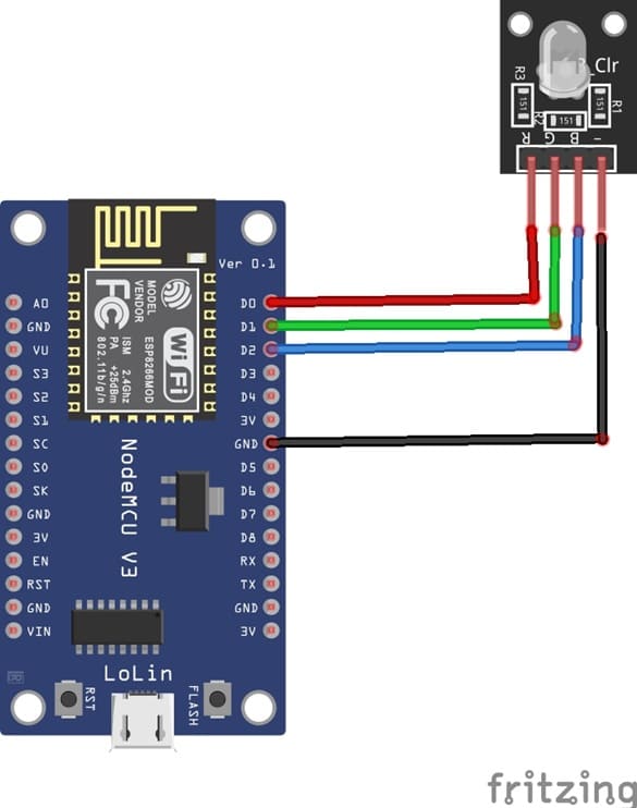
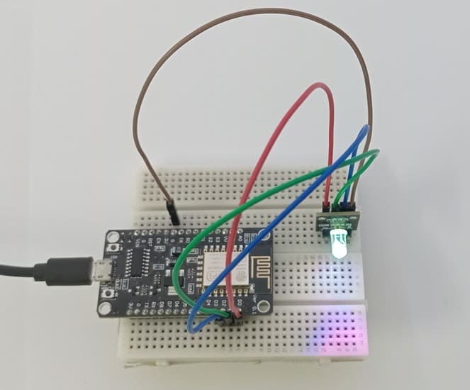
1- Connect pin R (red) of RGB LED module to D0 (GPIO16) of the ESP8266 board
2- Connect pin G (green) of RGB LED module to D1 (GPIO5) of the ESP8266 board
3- Connect pin B (blue) of RGB LED module to D2 (GPIO4) of the ESP8266 board
4- Connect pin GND of RGB LED module to pin GND of the ESP8266 board
Program ESP8266 NodeMCU with MicroPython
To program an ESP8266 board to turn on an RGB LED module using MicroPython, you'll need to follow these general steps:
1- Set up your development environment:
- Install MicroPython on your ESP8266 board. You can use tools like esptool to flash MicroPython firmware onto the board.
- Connect your ESP8266 board to your computer using a USB cable.
2- Write your MicroPython script: Create a Python script using a text editor or an integrated development environment (IDE). You can write this code on your computer and save it with a ".py" extension.
3- Import the necessary libraries:
- Import the machine module to control the GPIO pins on the ESP8266.
- Import the time module to control timing and delays.
Here's an example MicroPython script to control an RGB LED module:
|
1 2 3 4 5 6 7 8 9 10 11 12 13 14 15 16 17 18 |
from machine import Pin import time # define RGB LED pins red_color=Pin(16, Pin.OUT) green_color=Pin(5, Pin.OUT) blue_color=Pin(4, Pin.OUT) while True: blue_color.value(0) red_color.value(1) # Turn on the RGB LED in red time.sleep(2) # Wait for 2 seconds red_color.value(0) green_color.value(1) # Turn on the RGB LED in green time.sleep(2) # Wait for 2 seconds green_color.value(0) blue_color.value(1) # Turn on the RGB LED in blue time.sleep(2) # Wait for 2 seconds |
In this code, we set the pins GPIO16(D0), GPIO5(D1) and GPIO4(D2) as outputs to control the RGB LED. We then turn on the red channel and turn off the blue channel, creating a red color.
After two seconds, We then turn on the green channel and turn off the red channel. After two seconds, We then turn on the blue channel and turn off the green channel. The loop repeats, creating a blinking effect.
1 comment

Martina 23-03-2626
Having read this I thought it was extremely informative. I appreciate you taking the time and effort to put this informative article together. I once again find myself spending a lot of time both reading and leaving comments. But so what, it was still worthwhile!
Leave a comment
Passion for robotics

Recent tutorials
Robotics workshop

Polpular tutorials


Making robots

Most commented tutorials


Robotic arm

Categories
Smart Home