Display text on I2C LCD display via ESP8266 NodeMCU
Tutorial plan
1- Objective of the tutorial
2- The necessary components
3- ESP8266 Assembly with I2C LCD Display
4- Program ESP8266 NodeMCU with MicroPython
Objective of the tutorial
The objective of this tutorial is to learn how to display text messages on an I2C LCD display using the ESP8266 NodeMCU board.
Through this tutorial, you will understand how to connect the I2C LCD module to the ESP8266, install the necessary MicroPython libraries, and write a program to display and control text output.
By the end of this tutorial, you will be able to:
- understand the I2C communication protocol used by the LCD module.
- correctly wire the I2C LCD display to the ESP8266 NodeMCU board.
- write a MicroPython script to initialize the LCD and display custom messages.
- modify the program to scroll or update the text dynamically on the LCD screen.
The necessary components
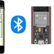
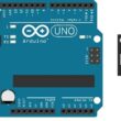
1- ESP8266 NodeMCU Board
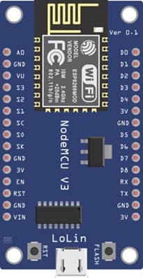
The ESP8266 NodeMCU is a Wi-Fi–enabled microcontroller board based on the ESP-12E module.
In this tutorial, it serves as the main controller that communicates with the I2C LCD display to send text for visualization.
2- I2C LCD Display (20x4)
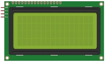
The I2C LCD display is a character LCD module that can display text, symbols, and messages.
The “I2C” version includes a small adapter module (usually based on the PCF8574 chip), which allows communication using only two wires (SDA and SCL) instead of multiple data pins.
This simplifies wiring and saves GPIO pins on the ESP8266.
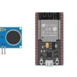
3- Breadboard
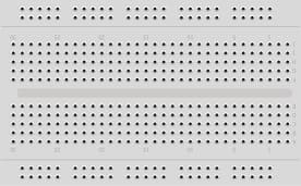
A breadboard is a prototyping platform used to connect components without soldering.
It helps in building temporary circuits by inserting jumper wires and module pins into its holes, making it ideal for testing and experimenting.
4- Jumper Wires
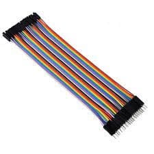
Jumper wires are flexible connectors used to make electrical connections between components on a breadboard.
In this tutorial, they connect the SDA, SCL, VCC, and GND pins of the LCD to the respective pins on the ESP8266 NodeMCU.
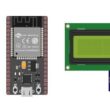
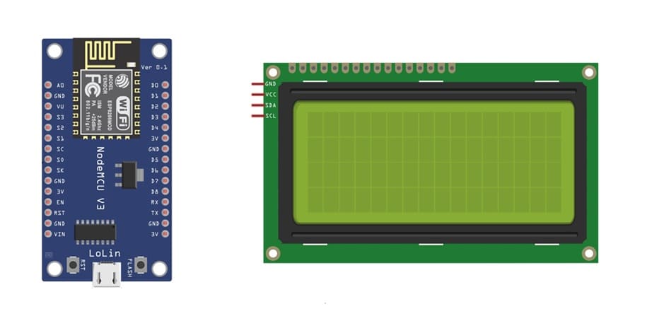
ESP8266 Assembly with I2C LCD Display
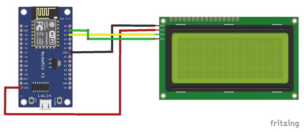
1- Connect the GND pin of the display to the GND pin of the ESP8266 board
2- Connect the VCC pin of the display to the VIN pin of the ESP8266 board
3- Connect the SDA pin of the display to the D2 (GPIO4) pin of the ESP8266 board
4- Connect the SCL pin of the display to the D1 (GPIO5) pin of the ESP8266 board
Program ESP8266 NodeMCU with MicroPython
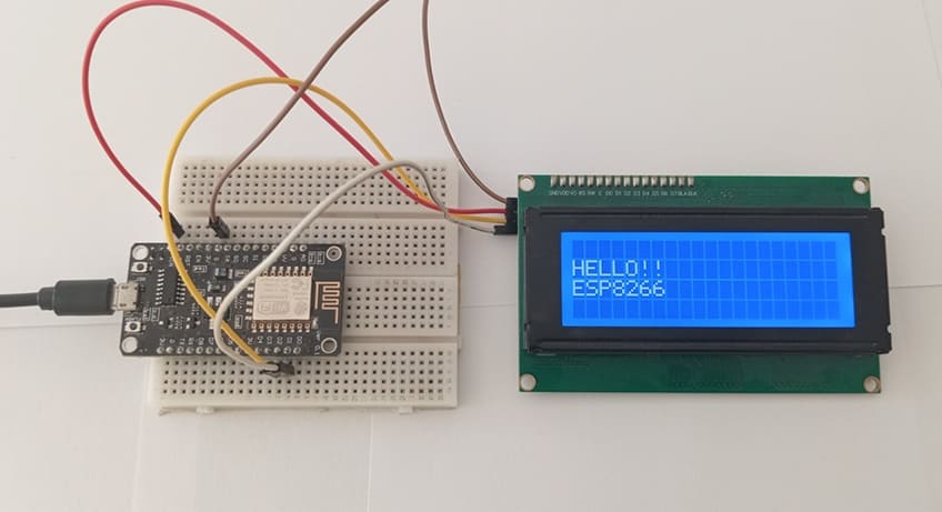
The program initializes the LCD, communicates via the I2C protocol, and displays a custom message.
Required libraries : i2c_lcd and lcd_api → to display information on the I2C LCD screen.
|
1 2 3 4 5 6 7 8 9 10 11 12 13 14 15 16 17 18 19 20 21 22 23 24 25 26 |
import machine from machine import Pin, SoftI2C from time import sleep from lcd_api import LcdApi from i2c_lcd import I2cLcd # Define LCD I2C address and size (20x4) I2C_ADDR = 0x27 totalRows = 4 totalColumns = 20 # Initialize I2C communication i2c = SoftI2C(scl=Pin(5), sda=Pin(4), freq=10000) #initializing the I2C method for ESP8266 lcd = I2cLcd(i2c, I2C_ADDR, totalRows, totalColumns) lcd.clear() while True: # Scroll text for i in range(14): lcd.move_to(i,1) lcd.putstr("HELLO!!") lcd.move_to(i,2) lcd.putstr("ESP8266") sleep(1) lcd.clear() |
Code Explanation
- I2C(scl=Pin(5), sda=Pin(4)) initializes I2C communication on the ESP8266 pins D1 and D2.
- I2cLcd(i2c, I2C_ADDR, 2, 16) creates an LCD object with 2 rows and 16 columns.
- lcd.putstr() writes a string on the display.
- lcd.clear() clears the screen.
- The while loop demonstrates how to scroll a message across the LCD.
0 comment
Leave a comment
Passion for robotics

Recent tutorials


Robotics workshop

Polpular tutorials


Making robots

Most commented tutorials


Robotic arm

Categories
Smart Home