Obstacle detection robot based on ESP32 and HC-SR04
Tutorial plan
1- What is an obstacle detection robot ?
2- Operation of the obstacle detection robot controlled by ESP32
3- Components Overview
4- Wiring Configuration
5- Micropython Code for ESP32
What is an obstacle detection robot ?
An obstacle detection robot is a type of robotic system designed to navigate environments while identifying and avoiding obstacles in its path. It typically uses sensors to detect objects, measure distances, and determine the best course of action to prevent collisions. Such robots are widely used in various applications, from autonomous vehicles to cleaning robots and industrial automation.
Key Features of an Obstacle Detection Robot
1- Sensors for Detection:
Ultrasonic Sensors: Emit sound waves and measure the time taken for the echoes to return, helping to calculate distances.
Infrared (IR) Sensors: Use infrared light to detect nearby objects.
LiDAR (Light Detection and Ranging): Provides precise distance measurement and 3D mapping of the surroundings.
Cameras: Help in visual object recognition and detection.
Bump Sensors: Trigger when physical contact with an obstacle occurs.
2- Control System:
Usually powered by a microcontroller (e.g., Arduino, Raspberry Pi) or a dedicated processor.
The system processes sensor data to identify obstacles and make navigation decisions.
3- Locomotion:
Wheels, tracks, or legs are used for movement. The choice depends on the terrain and application.
Motors (e.g., DC or stepper motors) drive the robot.
4- Obstacle Avoidance:
Algorithms such as pathfinding or reactive navigation guide the robot around obstacles.
Advanced robots use AI and machine learning for dynamic route planning.
Applications
Home Automation: Robotic vacuum cleaners like Roomba use obstacle detection to navigate around furniture and walls.
Autonomous Vehicles: Cars equipped with obstacle detection systems prevent collisions with pedestrians, other vehicles, or objects.
Industrial Automation: Robots in warehouses detect shelves, machinery, and humans to safely transport goods.
Search and Rescue: Robots navigate through debris in disaster zones, detecting obstacles like rubble and narrow pathways.
Agriculture: Autonomous robots avoid crops and other obstructions while performing tasks like harvesting or spraying.
Operation of the obstacle detection robot controlled by ESP32
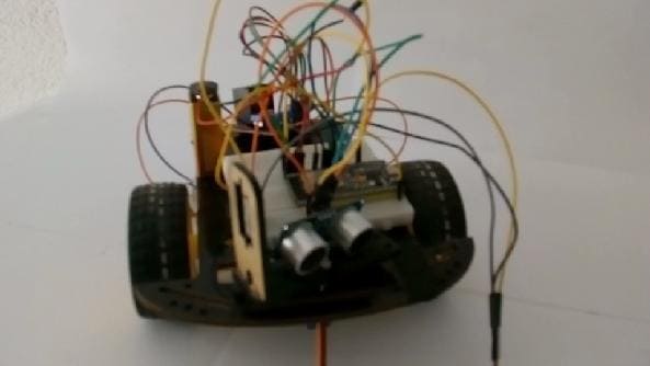
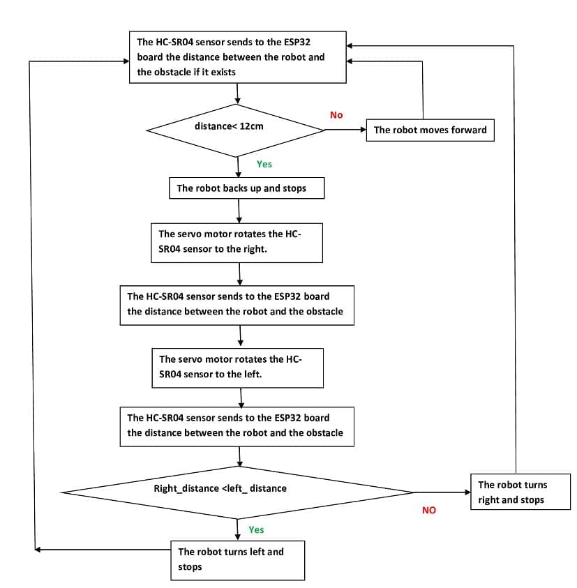
An obstacle detection robot with 2 wheels controlled by ESP32, HC-SR04 ultrasonic sensor, a servo motor, and L298D motor driver module operates by using the ultrasonic sensor mounted on a servo motor for dynamic obstacle detection. The servo motor rotates the ultrasonic sensor to scan the environment, while the L298D motor driver controls the robot's wheels for navigation.
1- Initialization:
The ESP32 initializes the HC-SR04 sensor, servo motor, and L298D motor driver.
The servo motor is set to its center position to start scanning.
2- Environment Scanning:
The servo motor rotates the HC-SR04 sensor to specific angles (e.g., 0°, 90°, and 180°) to measure distances at different directions.
The HC-SR04 sends distance data to the ESP32.
3- Obstacle Detection:
The ESP32 analyzes the distance data to determine the path:
Clear path ahead: The robot moves forward.
Obstacle detected ahead: The ESP32 compares the distances to the left and right.
If the left is clear, the robot turns left.
If the right is clear, the robot turns right.
If neither side is clear, the robot reverses or stops.
4- Motor Control:
Based on the decision, the ESP32 sends signals to the L298D motor driver to:
Move forward, backward, or stop.
Turn left or right by controlling the direction of the two motors.
5- Continuous Operation:
The robot continuously scans the environment, detects obstacles, and adjusts its movement.
Components Overview
ESP32:
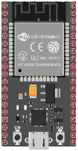
Microcontroller used to process data from the HC-SR04 sensor and control the L298D motor driver.
HC-SR04 Ultrasonic Sensor:
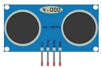
Detects obstacles by measuring the time it takes for sound waves to bounce back from objects.
Sends the measured distance data to the ESP32.
Servo Motor:

Rotates the ultrasonic sensor to scan left, center, and right for obstacle detection.
L298D Motor Driver Module:
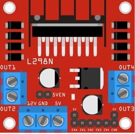
Interfaces between the ESP32 and the DC motors.
Controls the speed and direction of the motors based on commands from the ESP32.
DC Motors and Wheels:
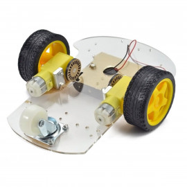
Provide locomotion for the robot.
Power Supply:
Batteries power the ESP32, motor driver, and motors (e.g., 7.4V or 12V battery for motors).
Jumper Wires:
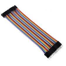
For making temporary connections and wiring between components.
Breadboard:
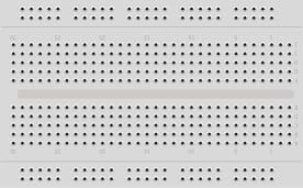
A breadboard is a useful tool for creating temporary electronic circuits. It allows you to connect components without soldering.
Wiring Configuration
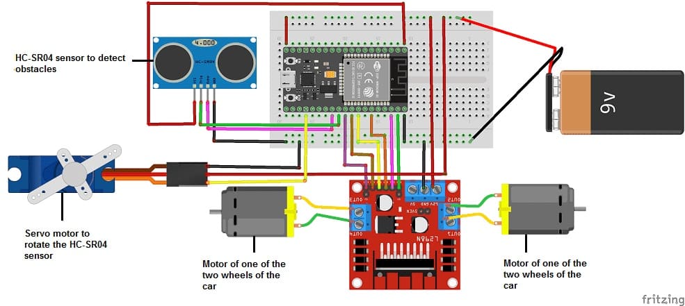
1- Servomotor to ESP32 :
Signal Pin: GPIO 15 (Configurable in code).
VCC: External 5V power supply.
GND: Common ground with ESP32.
1- HC-SR04 Ultrasonic Sensor to ESP32:
Trigger Pin: GPIO 17 (Configurable in code).
Echo Pin: GPIO 16 (Configurable in code).
VCC: 5V or 3V3 from ESP32 or external power source.
GND: Ground of ESP32.
2- L298D Motor Driver to ESP32:
IN1 (Motor A Forward): GPIO 22.
IN2 (Motor A Backward): GPIO 21.
IN3 (Motor B Forward): GPIO 19.
IN4 (Motor B Backward): GPIO 18.
ENA : GPIO 23
ENB : GPIO 5
Enable Pins (EN1/EN2): Connected to 5V or PWM pins for speed control.
VCC (Motor Supply): Connect to battery.
GND: Common ground with ESP32.
3- L298D to Motors:
Motor A: Connect one DC motor to OUT1 and OUT2.
Motor B: Connect the other DC motor to OUT3 and OUT4
Micropython Code for ESP32
Here’s an example code for controlling the robot:
You need to import DCMotor.py library to control the two motor and hc-sr04.py library to control the HC-SR04 sensors .
|
1 2 3 4 5 6 7 8 9 10 11 12 13 14 15 16 17 18 19 20 21 22 23 24 25 26 27 28 29 30 31 32 33 34 35 36 37 38 39 40 41 42 43 44 45 46 47 48 49 50 51 52 53 54 55 56 57 58 59 60 61 62 63 64 65 |
from hcsr04 import HCSR04 from DCMotor import DCMotor import machine from machine import Pin, PWM import time from time import sleep frequency = 15000 # Connect the ESP32 board to the L298N module pin1 = Pin(22, Pin.OUT) pin2 = Pin(21, Pin.OUT) pin3 = Pin(19, Pin.OUT) pin4 = Pin(18, Pin.OUT) enable = PWM(Pin(23), frequency) enable1 = PWM(Pin(5), frequency) dc_motor = DCMotor(pin1, pin2, enable) dc_motor = DCMotor(pin1, pin2, enable, 350, 1023) dc_motor1 = DCMotor(pin3, pin4, enable1) dc_motor1 = DCMotor(pin3, pin4, enable1, 350, 1023) # Connect the servo motor to the ESP32 board p15 = machine.Pin(15) servo = machine.PWM(p15,freq=50) servo.duty(70) # Connect the HC-SR04 sensor to the ESP32 board sensor = HCSR04(trigger_pin=17,echo_pin=16,echo_timeout_us=1000000) while True: distance = sensor.distance_cm() print(distance,' cm') if (distance<20): # if the HC-SR04 sensor detects an obstacle dc_motor.stop() # the robot car stops dc_motor1.stop() time.sleep_ms(1000) dc_motor.backwards(100) # the robot car backs up dc_motor1.backwards(100) time.sleep_ms(1000) dc_motor.stop() # the robot car stops dc_motor1.stop() time.sleep_ms(1000) for x in range(70,20,-1):# turn the HC-SR04 sensor to the right servo.duty(x) time.sleep_ms(50) distance_droite = sensor.distance_cm() time.sleep_ms(100) for x in range(20,110): # turn the HC-SR04 sensor to the left servo.duty(x) time.sleep_ms(50) distance_gauche = sensor.distance_cm() time.sleep_ms(1000) for x in range(110,70,-1): servo.duty(x) time.sleep_ms(100) if (distance_gauche < distance_droite) : # compare the two distances to choose the right direction dc_motor1.forward(100) # the robot car turns right time.sleep_ms(1000) dc_motor1.stop() time.sleep_ms(500) else: dc_motor.forward(100) # the robot car turn left time.sleep_ms(1000) dc_motor.stop() time.sleep_ms(500) else: dc_motor.forward(100) # the robot car moves forward dc_motor1.forward(100) time.sleep_ms(100) |


