Arduino Alarm Clock with DS1302 RTC Module
Tutorial plan
1- Objective of the project
2- Required Components
3- Circuit Connections of system
4- Arduino Alarm Clock program
Objective of the project
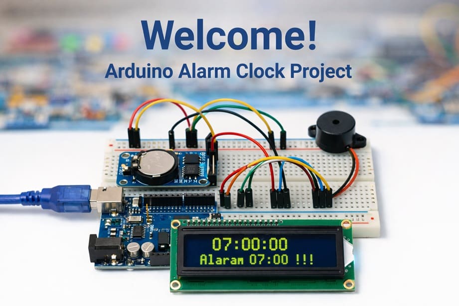
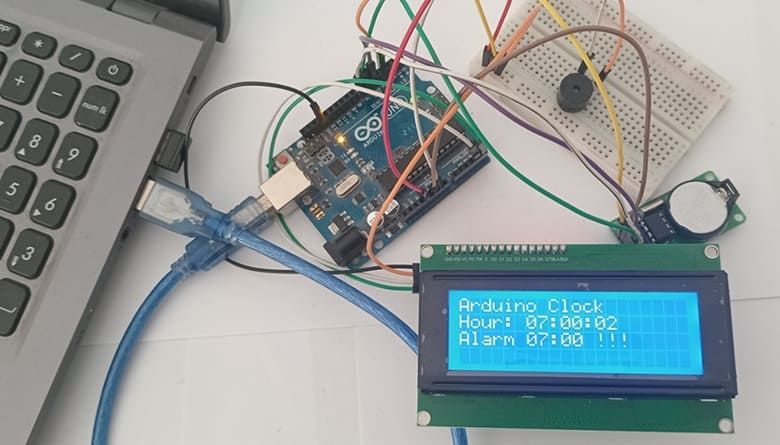
The objective of this project is to build a digital alarm clock using an Arduino, a DS1302 Real Time Clock (RTC) module, an I2C LCD display, and a buzzer. The system displays the current time in real time on the LCD and allows a predefined alarm time, such as 07:00:00, to be set in the program. When the alarm time is reached, the system alerts the user by displaying a warning message on the screen and activating the buzzer. This project demonstrates how to use an RTC module for accurate timekeeping and how to create a practical and interactive embedded system.
The functioning of the system is based on the Arduino continuously reading the current time from the DS1302 RTC module and displaying it on the LCD I2C screen. The Arduino compares the current time with the preset alarm time stored in the program. When both times match, the buzzer is activated and the LCD displays the message "Alarm 07:00 !!!" to notify the user. The RTC module ensures accurate timekeeping even when the main power is off, thanks to its backup battery, and the system continues to monitor and display the time continuously.
Required Components
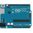
1. Arduino UNO
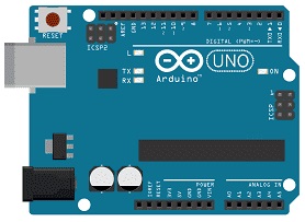
The Arduino Uno is the main controller of the system. It reads the current time from the RTC module, compares it with the preset alarm time, controls the LCD display, and activates the buzzer when the alarm time is reached. It acts as the brain of the entire alarm clock system.
2. DS1302 RTC Module
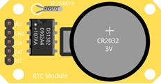
The Maxim Integrated DS1302 RTC (Real-Time Clock) module is used to keep track of the current time and date. It can store seconds, minutes, hours, day, month, and year. The module has a backup battery, which allows it to continue keeping time even when the Arduino is turned off. This ensures accurate and continuous timekeeping.
3. Buzzer
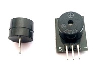
The buzzer is an output device that produces sound when the alarm time is reached. It alerts the user with an audible signal to indicate that the preset alarm time has occurred.
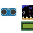
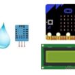
4. LCD Display with I2C Module

The LCD display shows the current time and the alarm message.
5. Jumper Wires

Jumper wires are used to connect the Arduino, RTC module, and LCD display together. They allow electrical signals and power to flow between the components.
6. Breadboard
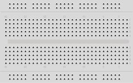
The breadboard is used to assemble the circuit without soldering. It allows easy connection of components and wires for prototyping.
Circuit Connections of system
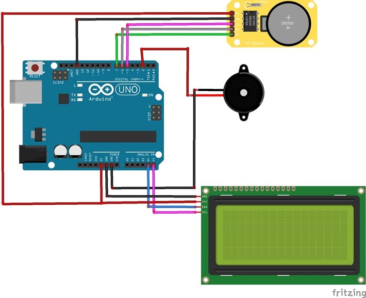
1- Connection of DS1302 RTC Module to Arduino UNO
| DS1302 RTC | Arduino UNO |
|---|---|
| CLK | pin 5 |
| DAT | pin 6 |
| RST | pin 7 |
| VCC | 5V |
| GND | GND |
2- Connection of LCD I2C display to Arduino UNO
| LCD display | Arduino UNO |
|---|---|
| VCC | 5V |
| GND | GND |
| SDA | pin A4 |
| SCL | pin A5 |
3- Conneciton of Buzzer to Arduino UNO
| Buzzer | Arduino UNO |
|---|---|
| Pin + | Pin 2 |
| Pin - | GND |
Arduino Alarm Clock program
This Arduino program implements a digital alarm clock using a DS1302 Real Time Clock (RTC) module, an I2C LCD display, and a buzzer.
You need to install this libraries :
LiquidCrystal_I2C for I2C LCD screen
ErriezDS1302-master for DS1302 RTC module
|
1 2 3 4 5 6 7 8 9 10 11 12 13 14 15 16 17 18 19 20 21 22 23 24 25 26 27 28 29 30 31 32 33 34 35 36 37 38 39 40 41 42 43 44 45 46 47 48 49 50 51 52 53 54 55 56 57 58 59 60 61 62 63 64 65 66 67 68 69 70 71 72 73 74 75 76 77 78 79 80 81 82 83 84 85 86 87 88 89 90 91 92 93 94 95 96 97 98 99 100 101 102 103 104 105 106 107 108 109 110 111 112 113 114 115 116 117 118 119 120 121 122 123 124 125 126 127 128 129 130 131 132 133 134 135 136 137 138 139 140 141 142 143 144 |
#include <ErriezDS1302.h> // Library for the DS1302 RTC module #include <LiquidCrystal_I2C.h> // Library for the I2C LCD display // =============================== // DS1302 RTC Configuration // =============================== #define CLK_PIN 5 // RTC CLK pin connected to Arduino digital pin D5 #define IO_PIN 6 // RTC DAT/IO pin connected to Arduino digital pin D6 #define CE_PIN 7 // RTC CE (Chip Enable) pin connected to Arduino digital pin D7 ErriezDS1302 rtc(CLK_PIN, IO_PIN, CE_PIN); // Create RTC object with defined pins // =============================== // I2C LCD 20x4 Configuration // =============================== LiquidCrystal_I2C lcd(0x27, 20, 4); // I2C address 0x27, LCD size: 20 columns x 4 rows int buzzerPin = 3; // Buzzer connected to Arduino digital pin D3 void setup() { pinMode(buzzerPin, OUTPUT); // Configure buzzer pin as output Serial.begin(9600); // Initialize serial communication (optional, for debugging) // Initialize the LCD display lcd.init(); // Initialize LCD lcd.backlight(); // Turn on LCD backlight lcd.clear(); // Clear LCD screen // Initialize the RTC module if (!rtc.begin()) { // Check if RTC module is detected lcd.setCursor(0, 0); lcd.print("RTC not detected"); // Display error message if RTC is not found while (1); // Stop program execution (infinite loop) } rtc.clockEnable(true); // Enable the RTC clock // ⚠️ Set the date and time ONLY ONCE, then comment this line // Format: hour, minute, second, day, month, year, weekday rtc.setDateTime(6, 59, 55, 8, 2, 2026, 1); // Example: Monday, February 8, 2026, 06:59:55 lcd.clear(); // Clear LCD after setting time } void loop() { uint8_t hour, min, sec, day, mon, wday; // Variables to store time and date values uint16_t year; // Variable to store year (16-bit) // Read current date and time from RTC module if (rtc.getDateTime(&hour, &min, &sec, &day, &mon, &year, &wday)) { // ================= DISPLAY CURRENT TIME ================= lcd.setCursor(0, 0); lcd.print("Arduino Clock"); // Display project title lcd.setCursor(0, 1); lcd.print("Hour: "); // Display hour with leading zero if needed if (hour < 10) lcd.print("0"); lcd.print(hour); lcd.print(":"); // Display minute with leading zero if needed if (min < 10) lcd.print("0"); lcd.print(min); lcd.print(":"); // Display second with leading zero if needed if (sec < 10) lcd.print("0"); lcd.print(sec); // ================= ALARM FUNCTION ================= // Check if current time matches alarm time (07:00:00) if ((hour == 7) && (min == 0) && (sec == 0)) { // Repeat alarm 10 times for (int i = 1; i <= 10; i++) { // Update and display current time during alarm if (rtc.getDateTime(&hour, &min, &sec, &day, &mon, &year, &wday)) { lcd.setCursor(0, 1); lcd.print("Hour: "); if (hour < 10) lcd.print("0"); lcd.print(hour); lcd.print(":"); if (min < 10) lcd.print("0"); lcd.print(min); lcd.print(":"); if (sec < 10) lcd.print("0"); lcd.print(sec); } // Display alarm message lcd.setCursor(0, 2); lcd.print("Alarm 07:00 !!!"); digitalWrite(buzzerPin, HIGH); // Turn buzzer ON delay(1000); // Wait 1 second // Update time and remove alarm message if (rtc.getDateTime(&hour, &min, &sec, &day, &mon, &year, &wday)) { lcd.setCursor(0, 1); lcd.print("Hour: "); if (hour < 10) lcd.print("0"); lcd.print(hour); lcd.print(":"); if (min < 10) lcd.print("0"); lcd.print(min); lcd.print(":"); if (sec < 10) lcd.print("0"); lcd.print(sec); } // Clear alarm message lcd.setCursor(0, 2); lcd.print(" "); digitalWrite(buzzerPin, LOW); // Turn buzzer OFF delay(1000); // Wait 1 second } } } else { // ================= ERROR HANDLING ================= lcd.clear(); lcd.setCursor(0, 0); lcd.print("Error RTC"); // Display error if RTC reading fails } delay(1000); // Wait 1 second before next RTC reading } |
0 comment
Leave a comment
Passion for robotics

Recent tutorials


Robotics workshop

Polpular tutorials


Making robots

Most commented tutorials


Robotic arm

Categories
Smart Home