Blink two LEDs by ESP8266 NodeMCU board
Tutorial plan
1- Objective of this tutorial
2- The components needed to control two LEDs by ESP8266 NodeMCU
3- Mounting ESP8266 NodeMCU card with two LEDs
4- Program ESP8266 NodeMCU with MicroPython
Objective of this tutorial
The objective of this tutorial is to learn how to control two LEDs using the ESP8266 NodeMCU development board. By the end of the tutorial, you will understand how to connect LEDs to the microcontroller, write a simple MicroPython program to make them blink alternately or simultaneously, and observe how digital output pins can be used for basic electronic control.
This exercise introduces beginners to the fundamentals of programming GPIO pins and lays the foundation for more advanced IoT and embedded systems projects.
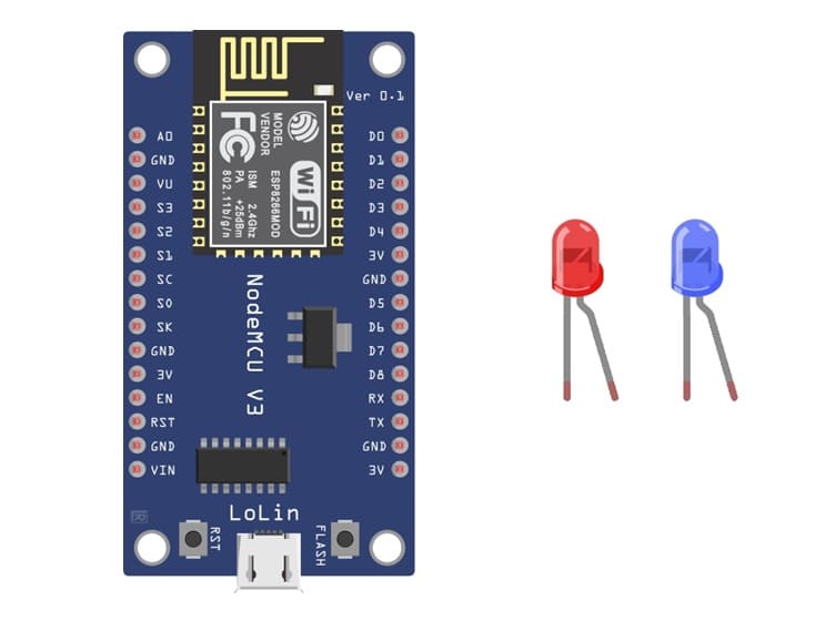
The components needed to control two LEDs by ESP8266 NodeMCU
1. ESP8266 NodeMCU Board
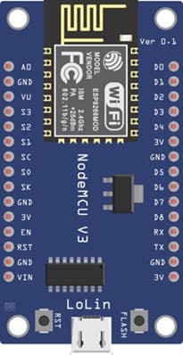
The main microcontroller that will be programmed to turn the LEDs on and off.
Two LEDs (Light Emitting Diodes)
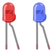
The output devices that will blink according to the program.
Two Resistors (220Ω – 330Ω)
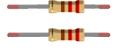
They are used in series with the LEDs to limit current and prevent them from burning out.
Breadboard
A prototyping board to easily connect all the components without soldering.
Jumper Wires
They make the electrical connections between the NodeMCU, resistors, and LEDs.
Mounting ESP8266 NodeMCU card with two LEDs
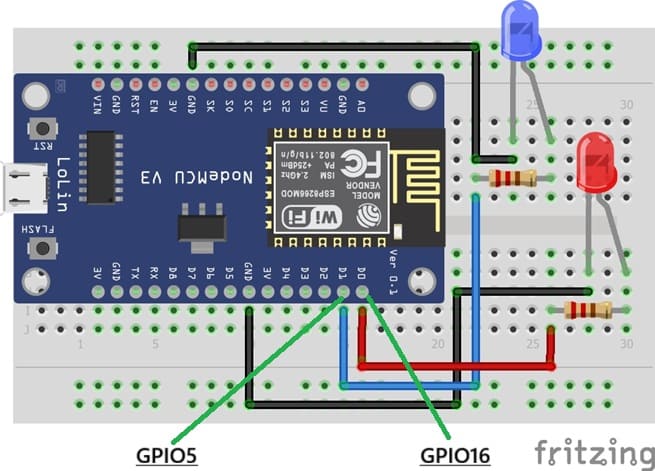
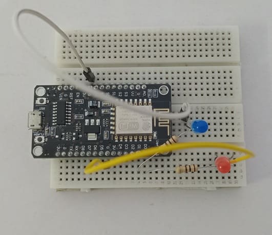
1- Place the NodeMCU on the Breadboard
2- Place the red LED on the breadboard.
3- The anode (long leg, +) will connect to one leg of a 220Ω resistor
4- The other leg of the resistor should go to D0 (DPIO16)
5- The cathode (short leg, –) will connect to GPIO pin of ESP8266
6- Place the blue LED on the breadboard.
7- The anode (long leg, +) will connect to one leg of a 220Ω resistor
8- The other leg of the resistor should go to D1 (DPIO5)
9- The cathode (short leg, –) will connect to GPIO pin of ESP8266
Program ESP8266 NodeMCU with MicroPython
|
1 2 3 4 5 6 7 8 9 10 11 12 13 14 15 16 17 |
from machine import Pin import time # Define LED pins (use GPIO numbers, not Dx labels) red_led = Pin(16, Pin.OUT) # D0 = GPIO16 blue_led = Pin(5, Pin.OUT) # D1 = GPIO5 while True: # Turn ON RED LED, OFF BLUE LED red_led.value(1) blue_led.value(0) time.sleep(2) # Turn OFF RED LED, ON BLUE LED red_led.value(0) blue_led.value(1) time.sleep(2) |
Explanation of the Program
from machine import Pin → Imports the Pin class to control GPIO pins.
import time → Used for delays (sleep function).
red_led = Pin(16, Pin.OUT) → Configures GPIO16 (D0) as output for the red LED.
blue_led = Pin(5, Pin.OUT) → Configures GPIO5 (D1) as output for the blue LED.
Inside the while True: loop, the LEDs blink alternately with a 2 second delay.
0 comment
Leave a comment
Passion for robotics

Recent tutorials


Robotics workshop

Polpular tutorials


Making robots

Most commented tutorials


Robotic arm

Categories
Smart Home