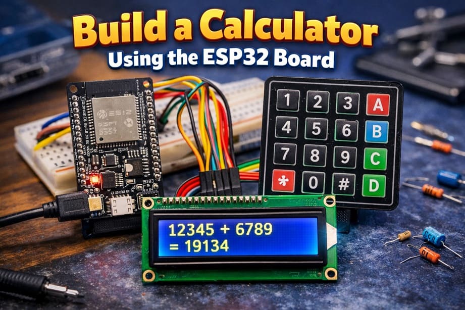
Build a Calculator Using the ESP32 Board
Tutorial plan
1- Objective of the project
2- Required Components
3- Circuit Connections of system
4- Micropython program of ESP32 calculator
Objective of the project
The objective of this project is to design and implement a functional digital calculator using the ESP32 microcontroller. The system allows the user to enter numbers and select arithmetic operations through a 4x4 matrix keypad, while the results are displayed clearly on an LCD I2C display.
This project aims to:
1- Understand how to interface a 4x4 matrix keypad with the ESP32 to detect user input.
2- Learn how to control an LCD I2C display to show numbers and calculation results.
3- Program the ESP32 using MicroPython to perform basic arithmetic operations such as addition, subtraction, multiplication, and division.
4- Practice embedded systems programming and hardware–software integration.
5- Develop problem-solving skills through real-time input processing and output display.
By completing this project, learners will gain practical experience in microcontroller programming, electronic circuit connections, and interactive embedded system design.
Required Components
1. BBC Micro:bit (Microcontroller)
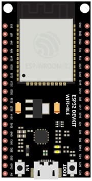
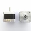
The ESP32 board is a small programmable microcontroller board designed for education. It acts as the main controller (brain) of the calculator.
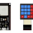
2. 4x4 Matrix Keypad
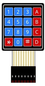
The 4x4 matrix keypad is used to input numbers and operations.
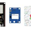
4. LCD Display with I2C Module

The LCD I2C display is used to show: entered numbers, mathematical operations and calculation results.
5. Breadboard

Breadboard is used for building a non-permanent circuit without soldering.
6. Jumper Wires

Jumper wires (male-to-male or male-to-female) are used to connect components to the ESP32 board.
Circuit Connections of system
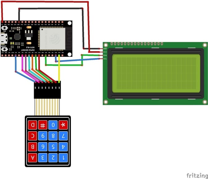

1- Connection of keypad to ESP32 board
| 4x4 Keypad | ESP32 board |
|---|---|
| R1 | GPIO23 |
| R2 | GPIO19 |
| R3 | GPIO18 |
| R4 | GPIO5 |
| C1 | GPIO17 |
| C2 | GPIO16 |
| C3 | GPIO4 |
| C4 | GPIO2 |
2- Connection of LCD I2C display to ESP32
| LCD I2C display | ESP32 |
|---|---|
| VCC | 5V |
| GND | GND |
| SDA | P20 |
| SCL | P19 |
Micropython program of ESP32 calculator
This program transforms the ESP32 into a functional calculator using a 4x4 matrix keypad for input and an I2C LCD display for output.
You need to install this libraries : i2c_lcd et lcd_api for I2C LCD screen.
|
1 2 3 4 5 6 7 8 9 10 11 12 13 14 15 16 17 18 19 20 21 22 23 24 25 26 27 28 29 30 31 32 33 34 35 36 37 38 39 40 41 42 43 44 45 46 47 48 49 50 51 52 53 54 55 56 57 58 59 60 61 62 63 64 65 66 67 68 69 70 71 72 73 74 75 76 77 78 79 80 81 82 83 84 85 86 87 88 89 90 91 92 93 94 95 96 97 98 99 100 101 102 103 104 105 106 107 108 109 110 111 112 113 114 115 116 117 118 119 120 |
# Import required libraries from machine import Pin, I2C # Used to control GPIO pins and I2C communication from i2c_lcd import I2cLcd # Library to control the I2C LCD display import time # Used for delays # ================= LCD I2C ================= # I2C address of the LCD module (commonly 0x27 or 0x3F) I2C_ADDR = 0x27 # Initialize the I2C bus: # I2C(0) -> I2C bus number 0 # scl=Pin(22) -> SCL connected to GPIO 22 # sda=Pin(21) -> SDA connected to GPIO 21 # 4, 20 -> LCD with 4 rows and 20 columns lcd = I2cLcd(I2C(0, scl=Pin(22), sda=Pin(21)), I2C_ADDR, 4, 20) # Clear the LCD screen lcd.clear() # Display startup message lcd.putstr("ESP32 Calculator") # ================= 4x4 KEYPAD ================= # Define the 4 keypad rows as outputs rows = [ Pin(23, Pin.OUT), Pin(19, Pin.OUT), Pin(18, Pin.OUT), Pin(5, Pin.OUT) ] # Define the 4 keypad columns as inputs # Pin.PULL_DOWN activates internal pull-down resistors # to prevent false signals columns = [ Pin(17, Pin.IN, Pin.PULL_DOWN), Pin(16, Pin.IN, Pin.PULL_DOWN), Pin(4, Pin.IN, Pin.PULL_DOWN), Pin(2, Pin.IN, Pin.PULL_DOWN) ] # Keypad layout (button mapping) keys = [ ['1', '2', '3', '+'], ['4', '5', '6', '-'], ['7', '8', '9', '*'], ['C', '0', '=', '/'] ] # Function to detect which key is pressed def read_key(): # Loop through each row for i in range(4): rows[i].on() # Activate one row at a time # Check each column for j in range(4): if columns[j].value(): # If a column detects a signal rows[i].off() # Deactivate the row return keys[i][j] # Return the corresponding key rows[i].off() # Deactivate the row before moving to the next one return None # No key pressed # ================= CALCULATOR ================= # Variable to store the typed mathematical expression expression = "" # Main loop (runs continuously) while True: # Read pressed key key = read_key() # If a key is detected if key: # Small delay to avoid double reading (debouncing) time.sleep(0.3) # If key is "C" → clear everything if key == 'C': expression = "" # Reset the expression lcd.clear() # Clear the display # If key is "=" → calculate the result elif key == '=': try: # Evaluate the mathematical expression result = str(eval(expression)) # Display the result lcd.clear() lcd.putstr("Result:") lcd.move_to(0, 1) # Move to second line lcd.putstr(result) # Allow continued calculation using the result expression = result except: # If error occurs (e.g., division by zero) lcd.clear() lcd.putstr("Error") expression = "" # Otherwise → add the pressed key to the expression else: expression += key # Append character lcd.clear() lcd.putstr(expression) # Small delay for stable reading time.sleep(0.1) |
0 comment
Leave a comment
Passion for robotics

Recent tutorials


Robotics workshop

Polpular tutorials


Making robots

Most commented tutorials


Robotic arm

Categories
Smart Home