Building a Smart Cooling System with ESP8266 and DHT11 Sensor
Tutorial plan
1- Objective of the tutorial
2- Operation of the cooling system
3- The necessary components
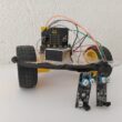
4- Cooling system installation
5- Program ESP8266 NodeMCU with MicroPython
Objective of the tutorial
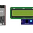
The aim of this tutorial is to develop a smart cooling system using the ESP8266 NodeMCU microcontroller, a DHT11 temperature and humidity sensor, a relay module, a 5V fan, and an LCD I2C display.
The system continuously monitors the ambient temperature through the DHT11 sensor and automatically activates or deactivates the fan via the relay module to maintain optimal cooling conditions.
The measured temperature and fan status are displayed on the LCD screen in real time.
Operation of the cooling system
The smart cooling system operates automatically based on the temperature readings from the DHT11 sensor. The ESP8266 NodeMCU continuously collects the temperature and humidity data from the sensor and compares the measured temperature with a predefined threshold value.
1- When the temperature exceeds the threshold (for example, 31 °C), the ESP8266 sends a signal to the relay module to activate the 5V fan. The fan starts running to cool down the environment.
2- As the temperature drops below the threshold, the ESP8266 deactivates the relay, which turns off the fan to save energy.
3- Throughout the process, the LCD I2C screen displays real-time information such as the current temperature, humidity, and the fan’s status (ON or OFF).
This automatic control provides an efficient and energy-saving way to maintain a stable temperature without requiring manual intervention.
The necessary components
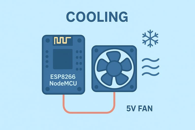
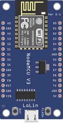
1- ESP8266 NodeMCU
It Serves as the main microcontroller that processes the temperature data from the DHT11 sensor and controls the relay and fan accordingly.
It Provides built-in Wi-Fi capability for future IoT extensions if desired.
2- DHT11 Temperature and Humidity Sensor
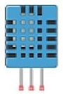
It Measures the ambient temperature and humidity.
It ends the measured data to the ESP8266 for decision-making.
3- Relay Module (5V)
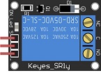
It acts as an electronic switch that allows the ESP8266 (low-voltage logic) to control the operation of the 5V fan.
It ensures electrical isolation between the microcontroller and the fan.
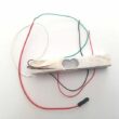
4- 5V DC Fan

It is used to cool down the environment when the temperature rises above the predefined limit.
It is controlled automatically through the relay module.
5- LCD I2C Display (16x2)

It displays the current temperature, humidity, and fan status (ON/OFF).
The I2C interface reduces the number of pins required for connection with the ESP8266.
6- Breadboard
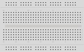
It is used for prototyping the circuit without soldering.
Allows easy insertion and connection of components.
7- Jumper Wires
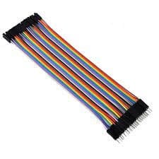
They ensure electrical connections between the ESP8266, sensor, buzzer, LED, and LCD display.
Cooling system installation
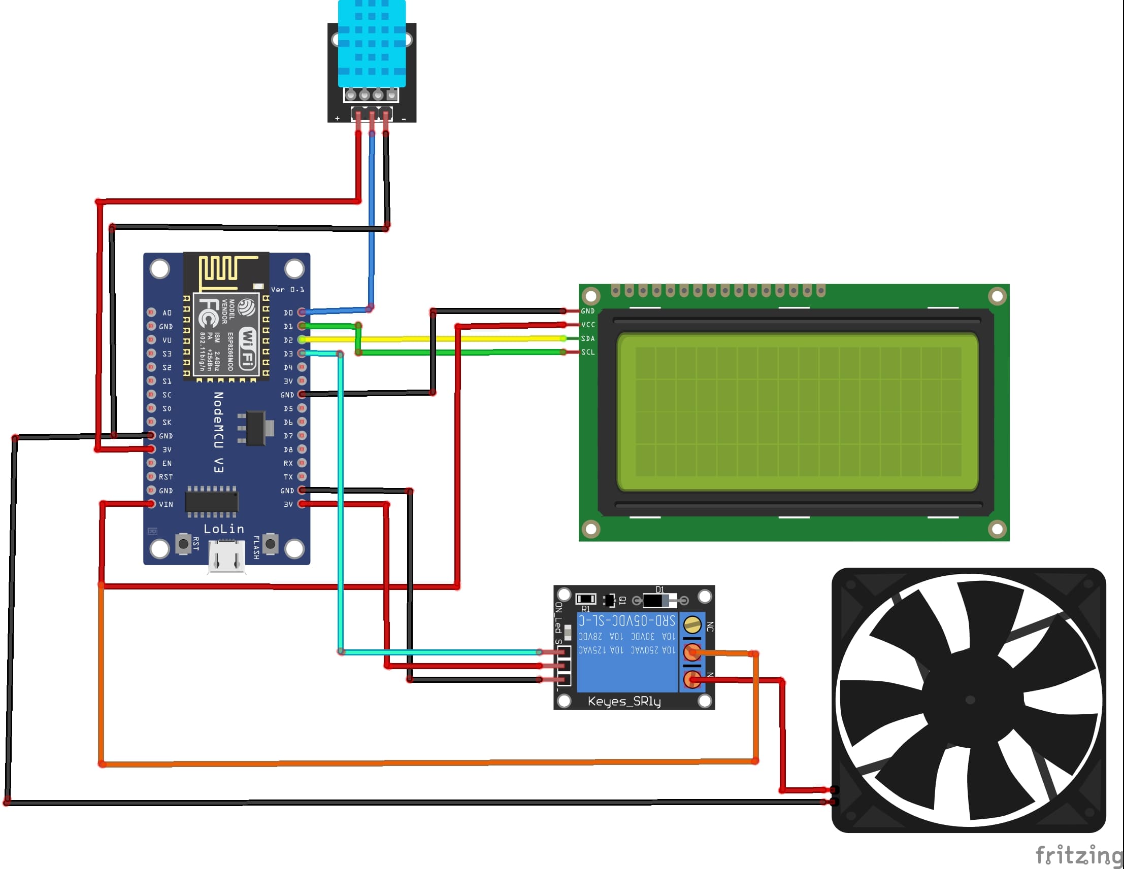
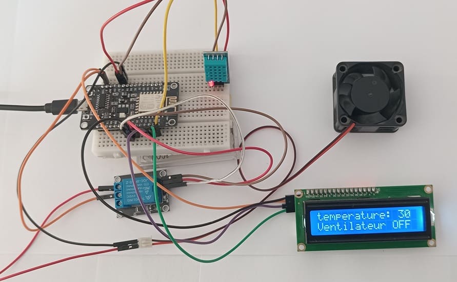
Attaching the I2C LCD Display :
- connect the VCC pin of the display to VIN (5V) pin of the ESP8266
- connect the GND pin of the display to GND pin of the ESP8266
- connect the SDA pin of the display to D2 (GPIO4) pin of the ESP8266
- connect the SCL pin of the display to D1 (GPIO5) pin of the ESP8266
Attaching the DHT11 Sensor:
- connect the VCC(+) pin of the DHT11 Sensor to 3V pin of the ESP8266
- connect the GND(-) pin of the DHT11 to GND pin of the ESP8266
- connect the DATA pin of the DHT11 to D0 (GPIO16) of the ESP8266
Attaching the relay module:
- connect the VCC(+) pin of the relay to 3V pin of the ESP8266
- connect the GND(-) pin of the relay to GND pin of the ESP8266
- connect the S pin of the relay to D5 (GPIO14) of the ESP8266
- connect the COM pin of the relay to VIN (5V) of the ESP8266
Attaching the fan:
- Connect the red (+) wire from the fan to the NO pin of the relay.
- Connect the black wire (-) from the fan to the GND pin of the ESP8266 board.
Program ESP8266 NodeMCU with MicroPython
Ensure you have the necessary libraries installed: dht, 'i2c_lcd' and 'lcd_api' for I2C LCD Screen.
|
1 2 3 4 5 6 7 8 9 10 11 12 13 14 15 16 17 18 19 20 21 22 23 24 25 26 27 28 29 30 31 32 33 34 35 36 37 38 39 40 |
import machine from machine import Pin, SoftI2C from lcd_api import LcdApi from i2c_lcd import I2cLcd from time import sleep import dht I2C_ADDR = 0x27 totalRows = 2 totalColumns = 16 # === Initialisation LCD I2C === i2c = SoftI2C(scl=Pin(5), sda=Pin(4), freq=10000) #initializing the I2C method for ESP8266 lcd = I2cLcd(i2c, I2C_ADDR, totalRows, totalColumns) #lcd2 = I2cLcd(i2c, I2C_ADDR, totalRows, totalColumns) p16=Pin(16, Pin.IN) # DHT11 Sensor Configuration d=dht.DHT11(p16) Configuring the relay module relay_pin=Pin(14, Pin.OUT) lcd.clear() while True: d.measure() t=d.temperature() #read temperature lcd.move_to(0,0) lcd.putstr("temperature: "+str(int(t))) # Display temperature on LCD display if (t>31) : # if temperature exceeds 31°C lcd.move_to(0,1) lcd.putstr("Ventilateur ON") # Display fan status on LCD display relay_pin.value(1) # Spin the fan else : lcd.move_to(0,1) lcd.putstr("Ventilateur OFF") # Display fan status on LCD display relay_pin.value(0) # Stop the fan sleep(2) lcd.clear() |
The Micropython program reads temperature and humidity values from the DHT11 sensor, displays them on the LCD screen, and automatically switches the fan on or off according to the set temperature limit.
0 comment
Leave a comment
Passion for robotics

Recent tutorials


Robotics workshop

Polpular tutorials


Making robots

Most commented tutorials


Robotic arm

Categories
Smart Home