Control a fan with ESP32 borad and relay module
Tutorial plan
1- How command a fan by ESP32 card ?
2- Components Needed
3- Circuit Setup
4- Programming ESP32 with Micropython
How command a fan by ESP32 card ?
To control a fan with an ESP32, a relay module, and a push button, you’ll create a circuit and code setup that toggles the fan on and off with each press of the button. The ESP32 microcontroller will read the button input and use the relay to switch the fan's power.
System Overview
1- ESP32: This microcontroller will monitor the push button and control the relay. The ESP32 will toggle the relay, which in turn controls the power to the fan.
2- Relay Module: This acts as a switch for the fan. Since the ESP32 operates on low voltage, it cannot directly drive the fan. The relay safely isolates the ESP32 from the higher power required by the fan.
3- Push Button: A simple push button acts as a manual control to toggle the fan on or off. Each button press changes the state of the relay and, consequently, the fan.
Components Needed
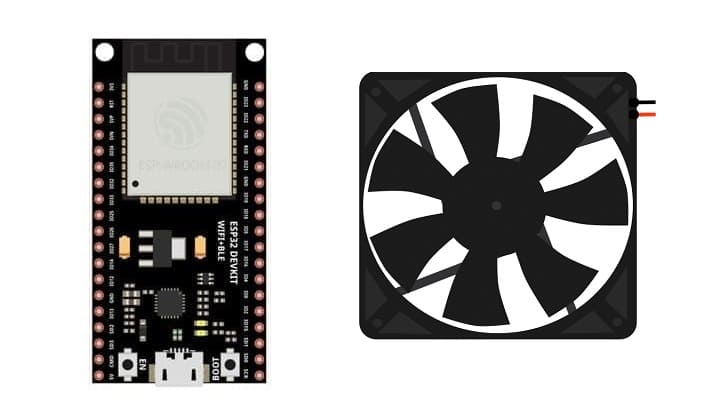
1- ESP32 board
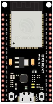
The ESP32 board is a microcontroller board that reads button inputs and controls the relay.
2- fan
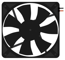
A fan is a mechanical device that creates a flow of air, often used for cooling, ventilation, or air circulation. Fans can be powered by electricity, batteries, or manually, and they come in various types and configurations depending on their purpose and power source.
3- Relay Module (for controlling the fan with ESP32):

A relay module allows the ESP32 to control a high-power device like a fun by isolating the fan's high voltage from the ESP32’s low voltage. When the ESP32 sends a signal, the relay switches on, allowing current to flow through the fan and activate it.
4- Push button:
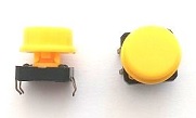
The push button is a simple input device that sends a signal to the ESP32 when pressed. The ESP32 detects button presses to toggle the relay.
4- Power supply for the water fan (matching the fan's requirements)
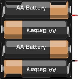
You’ll need a 4 x AAA batteries that provides enough current for the fan to operate effectively.
5- Jumper Wires
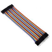
Jumper wires will be used to make connections between the components.
6- Breadboard:
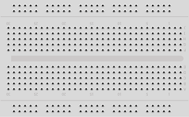
A breadboard can be used to create a temporary circuit for testing and prototyping.
Circuit Setup
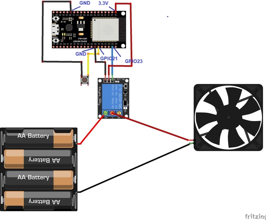
Connections:
1- Relay Module:
VCC: Connect to the ESP32’s 3.3V or 5V pin (depending on your relay module).
GND: Connect to the ESP32’s GND pin.
S pin: Connect to a GPIO pin on the ESP32 (e.g., GPIO 16).
ON pin: Connect to the (+) terminal of the 4 batteries
2- Fan and Power Supply:
Connect its positive lead to the relay’s NO terminal and the other lead to the negative terminal of the power supply.
4- Button Connections:
Connect one side of the button to GPIO 21 (or any other free GPIO pin) on the ESP32.
Connect the other side of the button to GND on the ESP32.
Programming the ESP32 with Micropython
The following code demonstrates toggling the fan state each time the button is pressed:
|
1 2 3 4 5 6 7 8 |
import machine button = machine.Pin(21, machine.Pin.IN, machine.Pin.PULL_UP) ventilateur=Pin(23,Pin.OUT) while True: if not button.value(): #We press the button ventilateur.value(1) #run the fan else: #We release the button ventilateur.value(0) #stop the fan |


