Control a lamp using an IR remote and ESP8266 NodeMCU
Tutorial plan
1- Objective of the tutorial
2- The necessary components
3- Assembly of the electronic system
4- Program ESP8266 NodeMCU with MicroPython
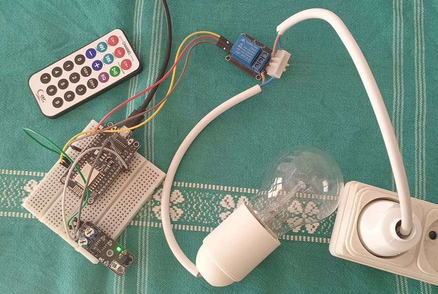
Objective of the tutorial
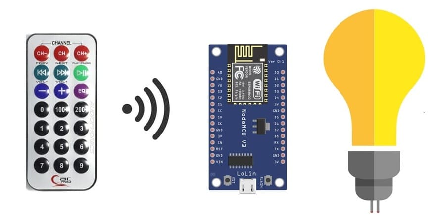
The objective of this tutorial is to control a lamp remotely using an infrared (IR) remote and an ESP8266 NodeMCU. The system allows you to turn the lamp ON or OFF by pressing specific buttons on the IR remote control. The ESP8266 NodeMCU receives the IR signals through an IR receiver, decodes them, and activates or deactivates a relay module connected to the lamp.
This project demonstrates how to:
- interface an IR receiver with the ESP8266 NodeMCU.
- decode the signals sent by an IR remote control.
- use the decoded IR codes to control a relay module.
- switch a lamp connected to a 220V power source safely through the relay.
The necessary components
1- ESP8266 NodeMCU Board
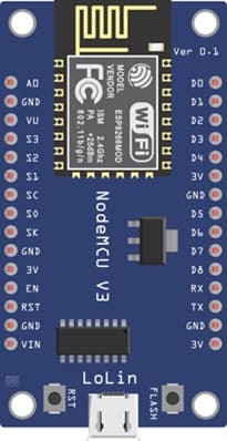
The main microcontroller that receives IR signals, processes them, and controls the relay module.
2- IR Receiver Module (KY-032)
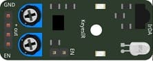
It detects and receives infrared signals sent by the IR remote control.
3- IR Remote Control

It is used to send IR signals to the receiver to turn the lamp ON or OFF.
4- Relay Module
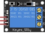
It acts as a switch to safely control the 220V AC lamp using the low-voltage signal from the ESP8266.
5- Lamp (220V)

The electrical load that will be turned ON or OFF by the relay.
4. Power Supply (220V AC)

It provides the electrical power needed to operate the lamp.
Wiring:

They safely connect a 220V AC lamp to a relay module that is controlled by the ESP8266 NodeMCU board.
6- Breadboard

It is used for making easy and temporary connections between components.
7- Jumper Wires
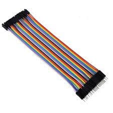
It is used for connecting the ESP8266 NodeMCU to the IR receiver and relay module.
Assembly of the electronic system
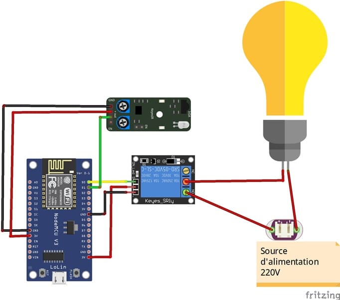
1- Connect the KY-032 infrared sensor to the ESP8266 board:
- Connect the VCC pin of the KY-032 sensor to the 3V pin on the ESP8266 board.
- Connect the GND pin of the KY-032 sensor to the GND pin on the ESP8266 board.
- Connect the OUT pin of the KY-032 sensor to a digital pin D1 (GPIO5) on the ESP8266 board.
2- Connect the Relay to the ESP8266 board:
- Connect the relay's control pin (S) to pin D0 (GPIO16) of ESP8266 board.
- Connect the pin (+) of relay to pin 3.3V of ESP8266 board.
- Connect the relay's ground pin (GND) to the ESP8266 board's GND.
3- Connect the Lamp and the power supply to the Relay:
- Connect one of the power supply's wires to the relay's common (COM) terminal.
- Connect the phase wire of the the lamp to the normally open (NO) terminal of the relay.
- Connect the neutral wire of the power supply directly to the neutral wire of the lamp.
Program ESP8266 NodeMCU with MicroPython
Here's a sample MicroPython code to read data from the KY-032 sensor and control the lamp based on its output:
You must install this library ir_rx to use for infrared remote signal reception and decoding.
|
1 2 3 4 5 6 7 8 9 10 11 12 13 14 15 16 17 18 19 20 21 22 23 24 25 26 27 28 29 30 31 32 |
import machine # Define the GPIO pins for the sensor and relay ir_sensor_pin = 5 # Connect KY-032 OUT pin to D1 pin relay_pin = 16 # Connect the relay to D0 pin # Set up the relay pin ir_sensor = machine.Pin(ir_sensor_pin, machine.Pin.IN) relay = machine.Pin(relay_pin, machine.Pin.OUT) # Function to capture and map IR codes def ir_callback(data, addr, ctrl): global ir_data global ir_addr if data > 0: ir_data = data ir_addr = addr print('Data {:02x} Addr {:04x}'.format(data, addr)) # Create the IR receiver object ir = NEC_16(ir_sensor, ir_callback) ir_data = 0 ir_addr = 0 # Main loop while True: if ir_data > 0: if ir_data==0x0C: # if you press button 1 on the remote control relay.value(1) # Turn on the lamp if ir_data==0x18: # if you press button 2 on the remote control relay.value(0) # Turn off the lamp ir_data = 0 |
0 comment
Leave a comment
Passion for robotics

Recent tutorials


Robotics workshop

Polpular tutorials


Making robots

Most commented tutorials


Robotic arm

Categories
Smart Home