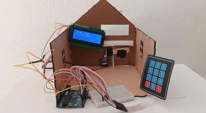
Door opening controlled by Arduino and 4×3 matrix keypad
Tutorial plan
1- Secure access system using digital keypad
2- How open a door using Arduino and 4x3 matrix keypad ?
3- Required Components
4- Circuit Connections of system
5- Arduino program of system
Secure access system using digital keypad
A secure access system using a digital keypad is an electronic security solution designed to restrict entry to a building, room, device, or system. Users must enter a correct numeric or alphanumeric password using a keypad to gain access. If the code entered is correct, the system unlocks a door, enables a device, or performs a predefined secure action. If the code is wrong, the system may deny access, sound an alarm, or lock the system temporarily.
The main goal of a secure access system is to control and monitor access to restricted areas, ensuring only authorized individuals can enter or use the system. These systems are commonly found in homes, office buildings, laboratories, server rooms, ATMs, and safes.
Working Principle
1- Input: The user enters a code via the keypad.
2- Processing:
The microcontroller reads the input.
It compares the entered code to a stored (preset) password.
3- Decision:
If the code matches: it activates a relay/servo motor to unlock a door or enable a system.
If the code is incorrect:
It may allow retrying a limited number of times.
It may activate a buzzer or alarm.
It may enter a lockout mode after repeated failures.
4- Feedback: The system provides real-time feedback through a display, buzzer, or LEDs.
Applications
- Home and office door locks
- School and university labs
- Lockers and safes
- Industrial machinery controls
- ATMs and banking terminals
- Hotel room access systems
How open a door using Arduino and 4x3 matrix keypad ?
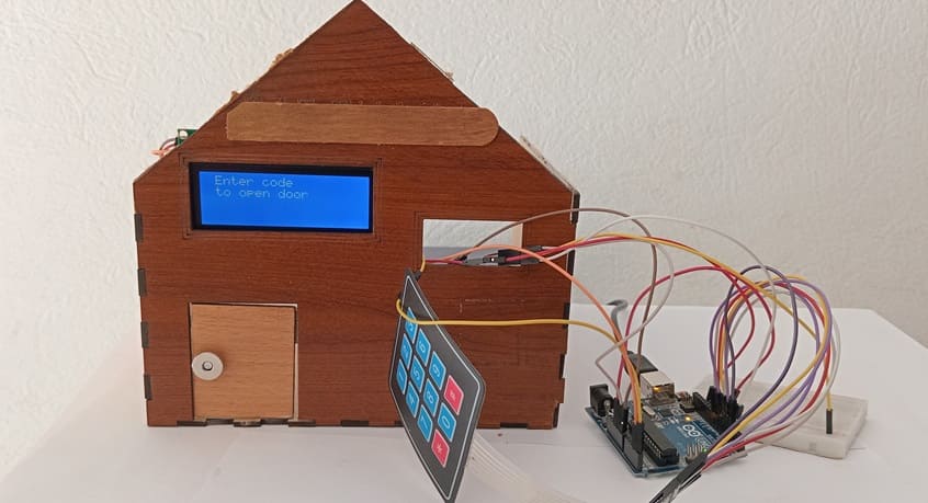
To build a secure access system that opens a door using a servo motor when a correct password is entered via a 4x3 matrix keypad. An LCD display provides visual feedback (e.g., password input, access granted or denied).
Working Principle:
1- User enters a password using the 4x3 keypad.
2- The Arduino compares the entered password with a predefined password stored in the code.
3- If the password is correct:
- LCD displays “Access Granted”
- Servo motor rotates to unlock position (e.g., 20°)
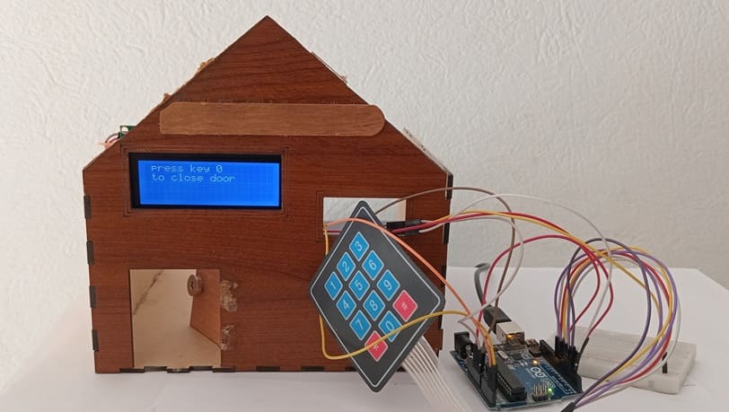
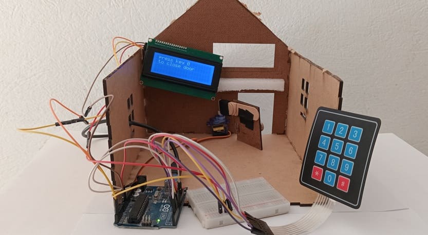
4- If we press the button 0 of keypad , it returns to the lock position (85°)
5- If the password is incorrect:
- LCD displays “Access Denied”
- System resets for a new attempt
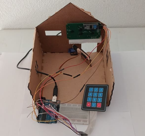
Required Components
1. Arduino UNO
Type: Microcontroller board based on the ATmega328P.
Function: Acts as the brain of the project. It reads the keypad input, processes the password, controls the servo motor, and updates the LCD.
2. 4x3 Matrix Keypad
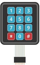
Type: 12-button membrane keypad arranged in 4 rows and 3 columns.
Function: Used for password input. Each key press is sent as a character (e.g., '1', '2', '#') to the Arduino.
3. 16x2 LCD Display (with I2C module)
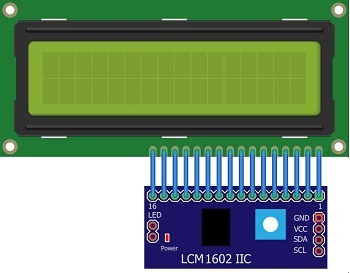
Type: Character LCD with 2 lines and 16 characters per line.
Function: Displays system status such as “Enter Password”, “Access Granted”, or “Access Denied”.
4. Servo Motor (e.g., SG90)

Type: Small 180° rotation hobby servo
Function: Simulates a door lock mechanism:
Rotates to 20° when access is granted (unlock)
Returns to 85° to close the door
5. Breadboard

Breadboard is used for building a non-permanent circuit without soldering.
6. Jumper Wires

Jumper wires (male-to-male or male-to-female) are used to connect components to the Micro:bit.
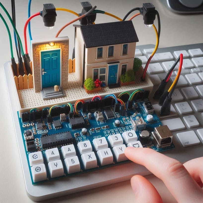
7. Wooden house prototype
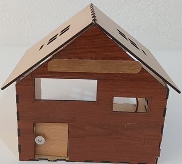
A miniature wooden house represents a real-world structure.
The door mechanism is attached to a servo motor, which rotates to open or close it.
The wooden prototype provides a stable frame for installing components like the IR sensor and LCD screen.
Circuit Connections of system
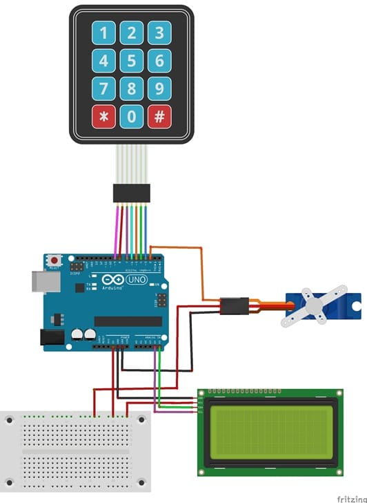
Connection of LCD I2C display to Arduino
LCD I2C Display Pin | Arduino Pin |
GND | GND |
VCC | 5V |
SDA | A4 |
SCL | A5 |
Connection of servo motor to Arduino
Servo motor | Arduino UNO |
Brown wire (-) | GND |
Red wire (+) | 5V |
Yellow wire (Signal) | D2 |
Connection of keypad to Arduino
4x3 Matrix Keypad | Arduino |
Pin 1 (right) | Pin 3 |
Pin 2 | Pin 4 |
Pin 3 | Pin 5 |
Pin 4 | Pin 6 |
Pin 5 | Pin 7 |
Pin 6 | Pin 8 |
Pin 7 | Pin 9 |
Arduino program of system
Here is a complete Arduino sketch for your Door Access Control System using keypad, I2C LCD, and Servo motor, with clear comments for each section:
This code uses the MFRC522 library for RFID communication and the LiquidCrystal_I2C library for the LCD display.
1- Open Arduino IDE.
2- Go to Sketch → Include Library → Manage Libraries.
3- Search for keypad and install it.
4- Search for LiquidCrystal_I2C and install it
|
1 2 3 4 5 6 7 8 9 10 11 12 13 14 15 16 17 18 19 20 21 22 23 24 25 26 27 28 29 30 31 32 33 34 35 36 37 38 39 40 41 42 43 44 45 46 47 48 49 50 51 52 53 54 55 56 57 58 59 60 61 62 63 64 65 66 67 68 69 70 71 72 73 74 75 76 77 78 79 80 81 82 83 84 85 86 87 88 89 90 91 92 93 94 95 96 97 98 99 100 101 102 103 104 105 106 107 108 109 110 111 112 113 114 115 116 117 118 119 120 121 122 123 124 125 |
// Include necessary libraries #include <LiquidCrystal_I2C.h> #include<Servo.h> //include the servo library #include <Keypad.h> const byte ROWS = 4; //four rows const byte COLS = 3; //three columns // Define keypad layout char keys[ROWS][COLS] = { {'1','2','3'}, {'4','5','6'}, {'7','8','9'}, {'*','0','#'} }; // Define the rows and columns for 4x3 keypad byte rowPins[ROWS] = {9, 8, 7, 6}; //connect to the row pinouts of the keypad byte colPins[COLS] = {5, 4, 3}; //connect to the column pinouts of the keypad //Create an object of keypad Keypad keypad = Keypad( makeKeymap(keys), rowPins, colPins, ROWS, COLS ); String code=""; String etoiles=""; // Initialize LCD at I2C address 0x27 with 20 columns and 4 rows LiquidCrystal_I2C lcd(0x27, 40, 4); // Create servo object Servo servo; //create a servo object int position_servo = 85; //initial position of the servo void setup() { // put your setup code here, to run once: // Initialize LCD servo.attach(2); //pin used by the servo servo.write(85); // rotate the servo motor to close the door lcd.init(); lcd.backlight(); lcd.clear(); lcd.setCursor(1, 0); lcd.print("Enter code"); lcd.setCursor(1, 1); lcd.print("to open door"); } void loop() { // put your main code here, to run repeatedly: // Read key from keypad char key = keypad.getKey(); if((key)) // If a key is pressed { if (key!='#') { lcd.setCursor(1, 2); etoiles=etoiles+"*"; lcd.print(etoiles); // Show stars on the LCD display code+=key; // store the values of the pressed buttons in the code variable delay(100); } else if (key=='#') { # if we presse the # button if (code=="1234") { # if the code is correct if (position_servo==85) { # if the door is closed lcd.clear(); lcd.setCursor(1, 1); lcd.print("The door opens"); for (int i=85; i>20 ; i--) { servo.write(i); # rotate the servo to open the door delay(100); } lcd.clear(); lcd.setCursor(1, 1); lcd.print("Door open"); delay(5000); lcd.clear(); lcd.setCursor(1, 0); lcd.print("press key 0"); lcd.setCursor(1, 1); lcd.print("to close door"); position_servo=20; } } else if (code=="0") { # if we press the button 0 if (position_servo==20) { # if the door is open lcd.clear(); lcd.setCursor(1, 1); lcd.print("The door closes"); for (int i=20; i<85 ; i++) { servo.write(i); # rotate the servo to close the door delay(100); } lcd.clear(); lcd.setCursor(1, 1); lcd.print("Door closed"); delay(5000); lcd.clear(); lcd.setCursor(1, 0); lcd.print("Enter code"); lcd.setCursor(1, 1); lcd.print("to open door"); position_servo=85; } } else { # if the code is invalid lcd.clear(); lcd.setCursor(1, 1); lcd.print("Invalid code"); delay(5000); lcd.clear(); lcd.setCursor(1, 0); lcd.print("Enter code"); lcd.setCursor(1, 1); lcd.print("to open door"); } code=""; etoiles=""; } } } |
0 comment
Leave a comment
Passion for robotics

Recent tutorials


Robotics workshop

Polpular tutorials


Making robots

Most commented tutorials


Robotic arm

Categories
Smart Home