Flame detection system using ESP8266 NodeMCU and KY-026 sensor
Tutorial plan
1- Objective of the tutorial
2- Operation of the flame detection system
3- The necessary components
4- System wiring diagram
5- Program ESP8266 NodeMCU with MicroPython
Objective of the tutorial
The main objective of this tutorial is to develop a flame detection system capable of identifying the presence of a flame or intense heat source using the KY-026 flame sensor, while employing the ESP8266 NodeMCU microcontroller for data processing and control.
This project aims to:
- detect a flame or fire in the environment by monitoring the analog and digital signals from the KY-026 sensor.
- use the ESP8266 NodeMCU to read sensor data and determine whether a flame is present.
- activate visual (LED) and audible (buzzer) indicators when a flame is detected, providing immediate alerts.
- display system status and sensor readings on an LCD I2C screen for real-time monitoring.
- demonstrate how the system can be easily integrated into a smart home or fire safety IoT project.
Through this tutorial, learners will understand the working principle of the KY-026 sensor, how to interface it with the ESP8266, and how to write a MicroPython program to control the alert mechanisms and display relevant data.
Operation of the flame detection system
The flame detection system works by continuously monitoring the environment for the presence of a flame or infrared (IR) light emitted by a fire source using the KY-026 flame sensor.
1- Flame Detection:
The KY-026 sensor detects infrared radiation within a wavelength range of approximately 760 nm to 1100 nm.
When a flame or heat source is brought near the sensor, it generates an analog signal proportional to the intensity of the detected light and a digital signal indicating the presence of a flame.
2- Signal Processing by ESP8266 NodeMCU:
The ESP8266 NodeMCU reads the analog value from the sensor through its ADC (analog-to-digital converter) pin.
It compares this value with a predefined threshold to determine whether a flame is detected.
3- Visual and Audible Alerts:
When a flame is detected, the LED turns ON to provide a visual indication.
Simultaneously, the buzzer is activated to generate an audible alarm, signaling the presence of fire or heat.
When no flame is present, the LED remains OFF and the buzzer stays silent.
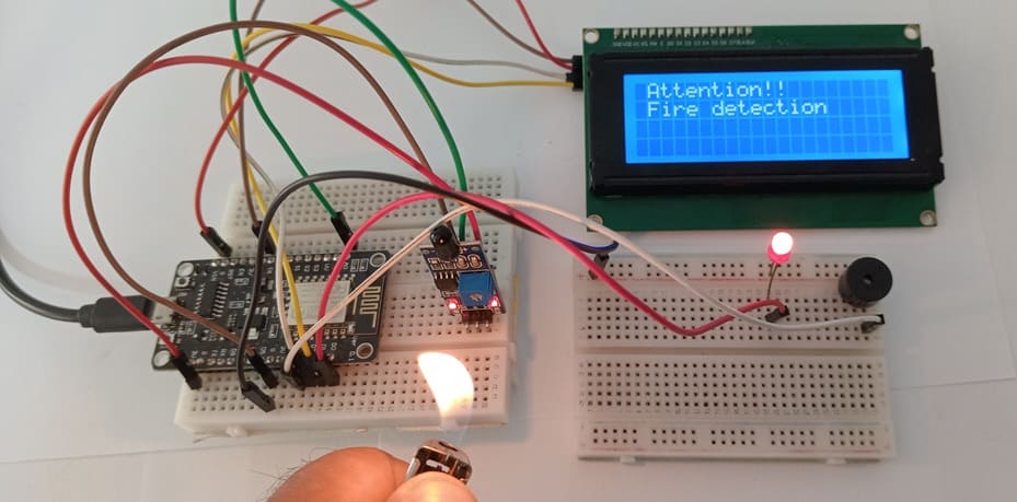
The I2C LCD screen displays alert message such as: “Flame Detected!”
The necessary components
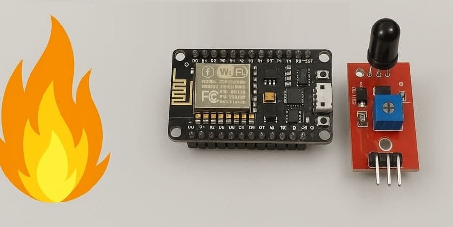
1- ESP8266 NodeMCU
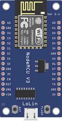
The ESP8266 NodeMCU is the main microcontroller that reads data from the KY-026 sensor, processes it, and controls the output devices (LED, buzzer, and LCD).
2- KY-026 Flame Sensor Module

The KY-026 Flame Sensor Module Detects the presence of a flame or infrared light and provides both analog and digital outputs.
3- I2C LCD Screen (20x4)
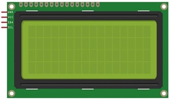
The I2C LCD Screen displays alert message such as: “Flame Detected!”.
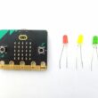
4- Red LED
![]()
The red LED serves as a visual indicator when a flame is detected.
5- Buzzer

The Buzzer produces an audible alarm to alert when the system detects a flame.
6- Breadboard (Plaque d’essai)

La plaque d'essai provides an easy platform for connecting all components without soldering.
7- Jumper Wires

The jumper wires are Used for making the necessary connections between the ESP8266, sensor, LED, buzzer, and LCD.
System wiring diagram
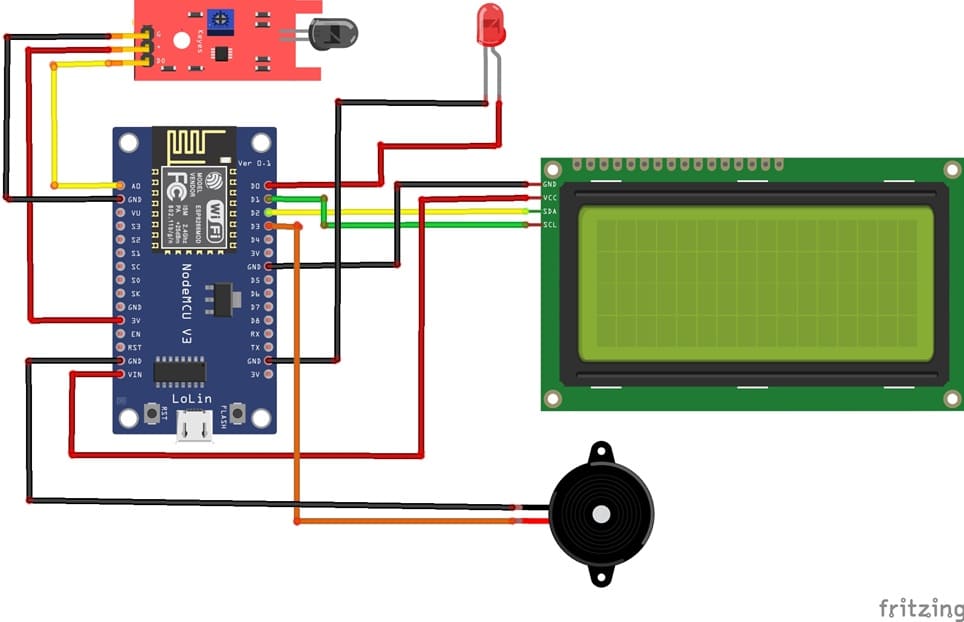
Attaching the I2C LCD Display :
- connect the VCC pin of the display to 5V pin of the ESP8266
- connect the GND pin of the display to GND pin of the ESP8266
- connect the SDA pin of the display to D2 (GPIO4) pin of the ESP8266
- connect the SCL pin of the display to D1 (GPIO5) pin of the ESP8266
Attaching the KY-026 Flame Sensor :
- Connect DO pin of the flame sensor to A0 pin of the ESP8266 board
- Connect the VCC (+) pin of the flame sensor to the 3V pin of the ESP8266 board
- Connect the GND(-) pin of the flame sensor to the GND pin of the ESP8266 board
Attaching the red LED :
- Connect the negative terminal (cathode) of each LED to the ground (GND) of the ESP8266 board.
- Connect the positive terminal (anode) of the LED to the D0 (GPIO16) pin of the ESP8266 board.
Attaching the buzzer :
- Connect the (+) terminal of buzzer to D3 (GPIO0) pin on the ESP8266 board.
- Connect the (-) terminal of buzzer to GND pin on the ESP8266 board.
Program ESP8266 NodeMCU with MicroPython
To program the flame detection system using ESP8266 NodeMCU, you'll need to follow these steps.
1- import this two libraries : i2c_lcd and lcd_api for I2C LCD screen
2- Create a new Python script and write the following code :
|
1 2 3 4 5 6 7 8 9 10 11 12 13 14 15 16 17 18 19 20 21 22 23 24 25 26 27 28 29 30 31 32 33 34 35 36 37 38 |
from machine import Pin, SoftI2C , ADC from lcd_api import LcdApi from i2c_lcd import I2cLcd from time import sleep I2C_ADDR = 0x27 totalRows = 4 totalColumns = 20 # Configure I2C for LCD screen i2c = SoftI2C(scl=Pin(5), sda=Pin(4), freq=10000) lcd = I2cLcd(i2c, I2C_ADDR, totalRows, totalColumns) # Configure buzzer and led pins redled_pin=Pin(16, Pin.OUT) buzzer_pin=Pin(0, Pin.OUT) # --- KY-026 Sensor Pins --- ky026_pin = ADC(0) while True: ky026_value = ky026_pin.read() if (ky026_value<100): # When flame is detected # Activate buzzer and LED redled_pin.value(1) buzzer_pin.value(1) # show alert message on LCD I2C display lcd.move_to(1,0) lcd.putstr("Attention!!") lcd.move_to(1,1) lcd.putstr("Incendie detectee") else: # Disable buzzer and LED redled_pin.value(0) buzzer_pin.value(0) lcd.clear() sleep(0.1) |
Explanation :
- The analog value gives the intensity of the flame.
- The digital output (DO) becomes LOW when a flame is detected.
- The LCD displays the status (“Flame Detected” or “No Flame”).
- The LED and Buzzer are activated when the flame is detected.
0 comment
Leave a comment
Passion for robotics

Recent tutorials


Robotics workshop

Polpular tutorials


Making robots

Most commented tutorials


Robotic arm

Categories
Smart Home