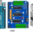
The L293D Motor Controller Shield Module
What is the L293D Motor Controller Shield Module ?
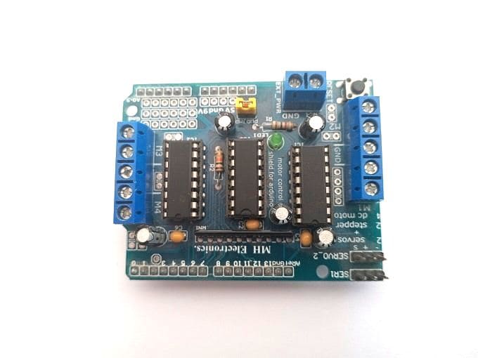
The L293D Motor Controller Shield Module is an electronic circuit board that is designed to control the speed and direction of DC motors. It is commonly used in robotics and automation projects, where precise control of motor movement is required.
The L293D chip on the module is a dual H-bridge driver, which means it can control the direction and speed of two separate motors simultaneously. Each motor output can handle a maximum current of 600 mA, with a peak current of up to 1.2 A. The module also includes a voltage regulator to supply power to the L293D chip and other components.
The module is typically controlled using digital signals from a microcontroller such as an Arduino or Raspberry Pi. By sending the appropriate signals to the module, the user can control the speed and direction of the connected motors. The module also includes protection diodes to prevent voltage spikes from damaging the connected motors or the L293D chip.
Composition of the L293D Shield Module
The L293D Motor Controller Shield Module typically consists of the following components:
L293D chip: This is the heart of the module and is a dual H-bridge driver, capable of controlling the direction and speed of two DC motors simultaneously.
Screw terminals: These are used to connect the power supply, motor, and other external components to the module.
Voltage regulator: This regulates the voltage supplied to the L293D chip and other components on the module.
LED indicators: These provide visual feedback on the status of the module, such as power and motor direction.
Protection diodes: These prevent voltage spikes and other electrical disturbances from damaging the connected motors or the L293D chip.
Header pins: These allow the module to be connected to a microcontroller or other external device, such as an Arduino or Raspberry Pi.
The module may also include other components, such as capacitors and resistors, that are used to stabilize the power supply and protect the circuitry. Overall, the composition of the L293D Motor Controller Shield Module may vary depending on the specific manufacturer and model.
L293D Shield Module Pins
The L293D Motor Controller Shield Module typically has the following pins:
VCC: This pin is used to supply power to the module. It should be connected to a voltage source between 5V and 12V.
GND: This pin is connected to the ground of the power supply.
Input pins: These pins are used to control the speed and direction of the connected motors. Each motor has two input pins: IN1 and IN2 for Motor 1, and IN3 and IN4 for Motor 2.
Output pins: These pins are connected to the terminals of the connected motors. Each motor has two output pins: OUT1 and OUT2 for Motor 1, and OUT3 and OUT4 for Motor 2.
Enable pins: These pins are used to enable or disable the motor outputs. Each motor has an enable pin: EN1 for Motor 1, and EN2 for Motor 2.
VCC2: This pin is used to supply power to the motor outputs. It should be connected to a voltage source that matches the voltage rating of the connected motors.
Ground pins: These pins are connected to the ground of the motor outputs.
The specific pinout of the L293D Motor Controller Shield Module may vary depending on the manufacturer and model, so it's important to consult the datasheet or documentation for the specific module being used.
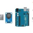
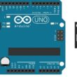
The L293D Shield module and the Aduino UNO board
The L293D Motor Controller Shield Module is often used with the Arduino UNO board, as it provides an easy and convenient way to control DC motors with the Arduino platform.
To use the L293D Shield module with the Arduino UNO, you would typically connect the following pins:
- VCC on the shield to 5V on the Arduino UNO.
- GND on the shield to GND on the Arduino UNO.
- IN1, IN2, EN1, OUT1, and OUT2 on the shield to digital pins on the Arduino UNO. The specific digital pins used will depend on the sketch being used, but the pins used must support pulse width modulation (PWM) to control the speed of the motors.
- IN3, IN4, EN2, OUT3, and OUT4 on the shield to different digital pins on the Arduino UNO that also support PWM.
Once the shield is connected to the Arduino UNO, you can use a compatible library or write your own code to control the speed and direction of the connected motors. This typically involves setting the appropriate digital pins high or low to control the direction, and using PWM to vary the speed of the motors.
Programming the L293D Shield module
To program the L293D Motor Controller Shield Module, you would typically use a programming language such as C++ and a compatible library such as the Arduino Motor Shield library. Here's an example code to control two DC motors connected to the L293D Shield module with an Arduino UNO:
|
1 2 3 4 5 6 7 8 9 10 11 12 13 14 15 16 17 18 19 20 21 22 23 24 25 26 27 28 29 30 31 32 33 34 35 36 37 38 39 40 41 |
#include <AFMotor.h> // Include the motor shield library AF_DCMotor motor1(1); // Create a motor object for motor 1 AF_DCMotor motor2(2); // Create a motor object for motor 2 void setup() { // Set up the motor shield AFMS.begin(); // Initialize the motor shield motor1.setSpeed(200); // Set the initial speed of motor 1 to 200 motor2.setSpeed(200); // Set the initial speed of motor 2 to 200 } void loop() { // Move both motors forward motor1.run(FORWARD); motor2.run(FORWARD); // Wait for 2 seconds delay(2000); // Stop both motors motor1.run(RELEASE); motor2.run(RELEASE); // Wait for 1 second delay(1000); // Move both motors backward motor1.run(BACKWARD); motor2.run(BACKWARD); // Wait for 2 seconds delay(2000); // Stop both motors motor1.run(RELEASE); motor2.run(RELEASE); // Wait for 1 second delay(1000); } |
In this example, the AFMotor.h library is used to create motor objects for motor 1 and motor 2, and the setup() function is used to initialize the motor shield and set the initial speed of both motors to 200. The loop() function then controls the movement of both motors, moving them forward for 2 seconds, stopping them for 1 second, moving them backward for 2 seconds, and stopping them for 1 second. The run() function is used to control the direction of the motors, with FORWARD and BACKWARD indicating the direction of movement, and RELEASE stopping the motors.
Role of Module Shield L293D in building robots
The L293D Motor Controller Shield Module is a useful component in building robots, as it provides a convenient way to control DC motors with an Arduino or other microcontroller. Here are some of the roles that the L293D Shield module can play in building robots:
1- Motor control: The L293D Shield module allows for easy control of DC motors, which are commonly used in robot designs. With the shield, you can control the speed and direction of the motors, making it possible to build robots that can move and perform a variety of tasks.
2- Power management: The shield can help manage the power supply for the connected motors, allowing for safe and efficient operation. The shield typically has separate power inputs for the motor and the microcontroller, which helps prevent the motor from interfering with the operation of the microcontroller.
3- Simplified wiring: The shield can simplify the wiring of a robot by providing a convenient interface between the microcontroller and the motors. This can reduce the amount of wiring required and make the overall design more compact and efficient.
4- Expandability: Many L293D Shield modules can be stacked on top of each other, allowing for the control of multiple motors with a single microcontroller. This can make it possible to build more complex robots with a greater range of motion and functionality.
0 comment
Leave a comment
Passion for robotics

Recent tutorials
Robotics workshop

Polpular tutorials


Making robots

Most commented tutorials


Robotic arm

Categories
Smart Home