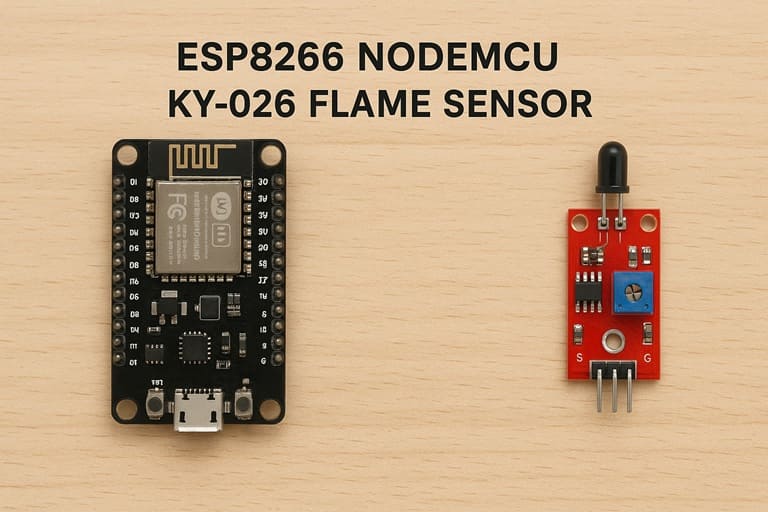
Using the KY-026 Flame Sensor with ESP8266 NodeMCU
Tutorial plan
1- Objective of the tutorial
2- Working principle of the KY-026 Flame Sensor
3- The necessary components
4- ESP8266 Assembly with I2C LCD Display and KY-026 Flame Sensor
5- Program ESP8266 NodeMCU with MicroPython
Objective of the tutorial
The main objective of this tutorial is to design and implement a flame detection system based on the KY-026 sensor, controlled by the ESP8266 NodeMCU microcontroller, and equipped with an LCD I2C screen for real-time data visualization.
This project aims to demonstrate how the KY-026 flame sensor can detect infrared light emitted by a flame and convert it into electrical signals that can be interpreted by the ESP8266.
The tutorial covers the connection of both analog and digital outputs of the KY-026 sensor to the ESP8266 to monitor varying flame intensities and detect the presence or absence of fire events.
The ESP8266 processes the sensor’s signals and displays the detection status or intensity level on the LCD I2C screen, offering immediate visual feedback to the user.
Working principle of the KY-026 Flame Sensor
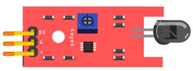
The KY-026 flame sensor operates based on the detection of infrared (IR) radiation emitted by a flame. Every flame produces a specific range of infrared light, typically around 760 nm to 1100 nm in wavelength. The sensor module is designed to detect this IR radiation and convert it into an electrical signal that can be processed by a microcontroller such as the ESP8266 NodeMCU.
The main sensing component on the KY-026 module is an infrared photodiode (or phototransistor) that reacts to the intensity of the infrared light. When a flame is present within the sensor’s field of view (usually up to 80–100 cm), the photodiode detects the IR radiation and changes its output voltage accordingly.
The module includes a comparator circuit (typically based on the LM393 operational amplifier) that compares the detected signal with a reference threshold set by the onboard potentiometer:
If the IR intensity from the flame exceeds the threshold, the digital output (DO) pin becomes LOW (indicating flame detection).
The analog output (AO) pin provides a variable voltage proportional to the detected IR intensity, allowing measurement of flame distance or strength.
The onboard indicator LED also turns ON when a flame is detected, providing a visual confirmation.
The necessary components
1- ESP8266 NodeMCU Board
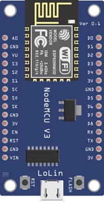
The ESP8266 NodeMCU Board acts as the main microcontroller that reads data from the KY-026 flame sensor and controls the LCD display.
It provides both analog (A0) and digital (GPIO) pins for input, as well as I2C communication for the LCD.
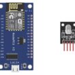
2- KY-026 Flame Sensor Module
The KY-026 flame sensor detects infrared radiation emitted by flames.
It provides both analog output (DO) for measuring flame intensity and digital output (DO) for threshold-based flame detection.
It is equipped with a potentiometer to adjust the detection sensitivity and a comparator circuit for signal conditioning.
3- LCD I2C Screen (20x4)
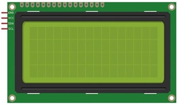
The LCD I2C Screen displays the flame detection status and sensor readings in real time.
It uses an I2C interface (SDA, SCL) which reduces the number of pins required for connection to the ESP8266.
It makes it easy to visualize data such as “Flame Detected” or “No Flame Detected.”
4- Connecting Wires
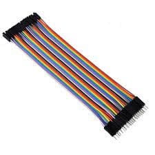
The Connecting Wires is used to connect the flame sensor and LCD I2C module to the ESP8266 on a breadboard or directly through pin headers.
They Ensure solid and correct electrical connections between components.
5- Breadboard
The breadboard provides a convenient platform for prototyping the circuit without soldering.
It Allows easy rearrangement or modification of component connections.
ESP8266 Assembly with I2C LCD Display and KY-026 Flame Sensor
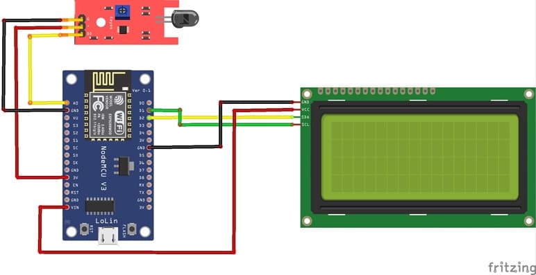
Attaching the I2C LCD Display :
- connect the VCC pin of the display to 5V pin of the ESP8266
- connect the GND pin of the display to GND pin of the ESP8266
- connect the SDA pin of the display to D2 (GPIO4) pin of the ESP8266
- connect the SCL pin of the display to D1 (GPIO5) pin of the ESP8266
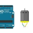
Attaching the KY-026 Flame Sensor :
- Connect DO pin of the flame sensor to A0 pin of the ESP8266 board
- Connect the VCC (+) pin of the flame sensor to the 3V pin of the ESP8266 board
- Connect the GND(-) pin of the flame sensor to the GND pin of the ESP8266 board
Program ESP8266 NodeMCU with MicroPython
To program the ESP8266 board with MicroPython to reads the DO output of the KY-026 and show value on an I2C 20×4 LCD, you can follow the steps below.
1- import this two libraries : i2c_lcd and lcd_api for I2C LCD screen
2- Create a new Python script and write the following code :
|
1 2 3 4 5 6 7 8 9 10 11 12 13 14 15 16 17 18 19 20 21 22 23 24 25 26 27 28 |
from machine import Pin, SoftI2C , ADC from lcd_api import LcdApi from i2c_lcd import I2cLcd from time import sleep I2C_ADDR = 0x27 totalRows = 4 totalColumns = 20 # Configure I2C for LCD screen i2c = SoftI2C(scl=Pin(5), sda=Pin(4), freq=10000) lcd = I2cLcd(i2c, I2C_ADDR, totalRows, totalColumns) # Configure KY-026 sensor ky026_pin = ADC(0) while True: # Read analog value sent by the KY-026 sensor ky026_value = ky026_pin.read() lcd.move_to(0,0) lcd.putstr("KY-026") lcd.move_to(0,1) lcd.putstr("Analog value") lcd.move_to(1,2) # Display analog value sent by the KY-026 sensor lcd.putstr(str(ky026_value)) sleep(1) lcd.clear() |
Code Explanation:
ADC(0): Configures the A0 input of the ESP8266 board to read an analog voltage.
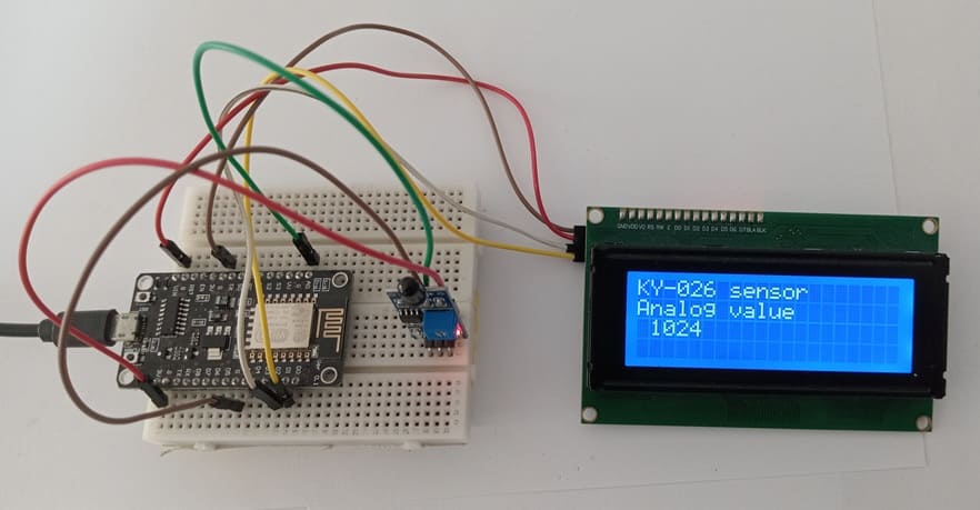
read(): Returns a value between 0 and 1023 depending on the intensity of the infrared light detected by the sensor.
High value (near 1024) → low flame intensity or no flame.
Low value (near 0) → flame detected nearby.
The while True loop allows for continuous reading and real-time display on the I2C LCD.
0 comment
Leave a comment
Passion for robotics

Recent tutorials


Robotics workshop

Polpular tutorials


Making robots

Most commented tutorials


Robotic arm

Categories
Smart Home