Create Your Own Speed Radar with Micro:bit and HC-SR04
Tutorial plan
1- Objective of the project
2- Required Components
3- Circuit Connections of system
4- Micropython program of Micro:bit
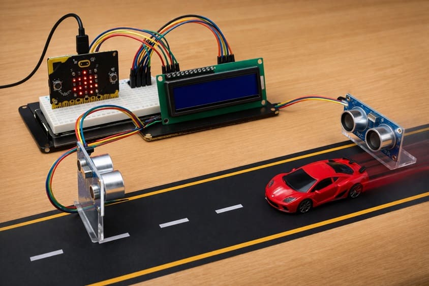
Objective of the project
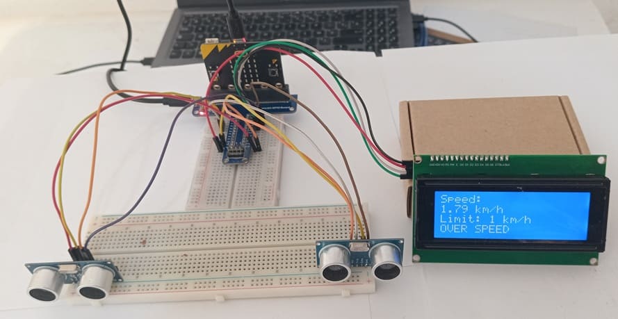
The primary goal of this project is to build a compact, portable speed radar system using the Micro:bit microcontroller, a HC-SR04 ultrasonic distance sensor, an I2C LCD display, and a buzzer. This system aims to detect the speed of moving objects in real time and provide both visual and audible feedback. By combining these components, users can learn how distance measurements and timing calculations translate into speed detection, while also exploring programming logic and embedded electronics principles. This project is suitable for educational purposes, experimentation, and hobbyist applications where understanding motion detection and microcontroller interfacing is the main focus.
Functioning:
The speed radar operates by using the HC-SR04 ultrasonic sensor to measure the distance between the sensor and a moving object at two consecutive points in time. The Micro:bit calculates the object's speed using the difference in distance over the measured time interval. The calculated speed is then displayed on the I2C LCD, providing an immediate visual output. Additionally, a buzzer is integrated to signal when an object exceeds a predefined speed threshold, giving instant audible feedback. The program running on the Micro:bit continuously monitors the sensor data, updates the LCD, and controls the buzzer, allowing the system to function autonomously and accurately detect object motion in real time.
Required Components
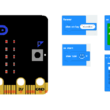
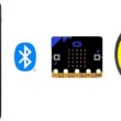
1. BBC Micro:bit (Microcontroller)

The Micro:bit serves as the main processing unit. It reads data from the ultrasonic sensor, performs speed calculations, controls the LCD display, and activates the buzzer.
2. GPIO Extension Card for Micro:bit

The GPIO extension card Expands the number of usable input/output pins on the Micro:bit, making it easier to connect multiple components.
3. HC-SR04 sensor
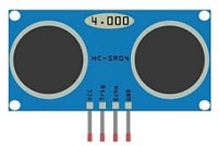
This sensor measures distance by emitting ultrasonic waves and calculating the time it takes for the echo to return. In this project, it is used to measure the position of a moving object at two time intervals, which allows the Micro:bit to compute the object’s speed.
4. LCD Display with I2C Module

The I2C LCD screen is used to display real-time information such as the measured speed, system status, and warning messages.
5. Breadboard

A breadboard is used to assemble the circuit without soldering. It makes it easy to connect and modify the components during testing and development.
6. Jumper Wires

Jumper wires are used to connect the Micro:bit, HC-SR04 sensors, and LCD display together. They ensure proper electrical connections between all components.
Circuit Connections of system
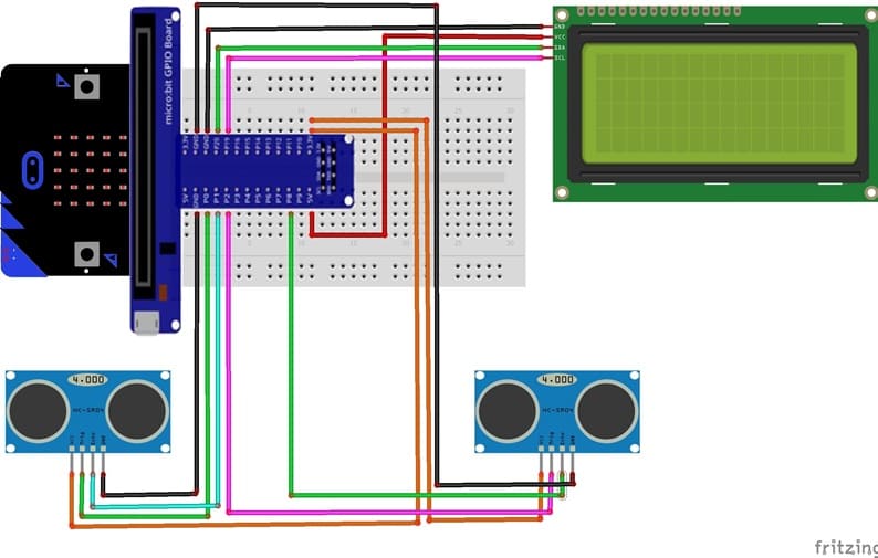
1- Connecting the first HC-SR04 sensor to the Micro:bit board
| HC-SR04 | Micro:bit |
|---|---|
| VCC | 3.3 V |
| Trig | P0 |
| Echo | P1 |
| GND | GND |
2- Connecting the second HC-SR04 sensor to the Micro:bit board
| HC-SR04 | Micro:bit |
|---|---|
| VCC | 3.3 V |
| Trig | P2 |
| Echo | P8 |
| GND | GND |
3- Connection of LCD I2C display to Micro:bit
| LCD I2C display | Micro:bit board |
|---|---|
| VCC | 5V of GPIO card |
| GND | GND |
| SDA | P20 |
| SCL | P19 |
Micropython program of Micro:bit
This Micropython program turns a Micro:bit into a simple speed radar using two HC-SR04 ultrasonic sensors, an I2C LCD display, and a buzzer. It measures the time an object takes to travel between two points and calculates its speed. The results are displayed on the LCD, and a buzzer alerts when the speed exceeds a set limit.
|
1 2 3 4 5 6 7 8 9 10 11 12 13 14 15 16 17 18 19 20 21 22 23 24 25 26 27 28 29 30 31 32 33 34 35 36 37 38 39 40 41 42 43 44 45 46 47 48 49 50 51 52 53 54 55 56 57 58 59 60 61 62 63 64 65 66 67 68 69 70 71 72 73 74 75 76 77 78 79 80 81 82 83 84 85 86 87 88 89 90 91 92 93 94 95 96 97 98 99 100 101 102 103 104 105 106 107 108 109 110 111 112 113 114 115 116 117 118 119 120 121 122 123 124 125 126 127 128 129 130 131 132 133 134 135 136 137 138 139 140 141 142 143 144 145 146 147 148 149 150 151 152 153 154 155 156 157 158 159 160 161 162 163 164 165 166 167 168 |
from microbit import * import utime import music # ========================= # CONFIGURATION # ========================= DISTANCE = 0.20 # Distance between sensor 1 and sensor 2 in meters THRESHOLD = 10 # Object detection threshold in cm SPEED_LIMIT = 1 # Maximum allowed speed in km/h I2C_ADDR = 0x27 # I2C address of the LCD display # ========================= # LCD I2C (PCF8574) FUNCTIONS # ========================= def lcd_write(cmd, mode=0): """Send a byte to the LCD using two 4-bit transfers.""" high = cmd & 0xF0 low = (cmd << 4) & 0xF0 lcd_byte(high | mode) lcd_byte(low | mode) def lcd_byte(data): """Write a single byte to the LCD via I2C with enable pulse.""" i2c.write(I2C_ADDR, bytearray([data | 0x08])) # Enable low->high utime.sleep_us(50) i2c.write(I2C_ADDR, bytearray([data | 0x0C])) # Enable high utime.sleep_us(50) i2c.write(I2C_ADDR, bytearray([data | 0x08])) # Enable low utime.sleep_us(50) def lcd_cmd(cmd): """Send a command byte to the LCD.""" lcd_write(cmd, 0) def lcd_data(data): """Send a data byte (character) to the LCD.""" lcd_write(data, 1) def lcd_init(): """Initialize the LCD in 4-bit mode.""" utime.sleep_ms(50) lcd_cmd(0x33) lcd_cmd(0x32) lcd_cmd(0x28) # 4-bit mode, 2 lines, 5x8 font lcd_cmd(0x0C) # Display on, cursor off lcd_cmd(0x06) # Entry mode: increment cursor lcd_cmd(0x01) # Clear display utime.sleep_ms(5) def lcd_clear(): """Clear the LCD display.""" lcd_cmd(0x01) utime.sleep_ms(5) def lcd_move(col, row): """Move cursor to a specific column and row.""" addr = [0x80, 0xC0, 0x94, 0xD4] lcd_cmd(addr[row] + col) def lcd_puts(text): """Display a string on the LCD at current cursor position.""" for c in text: lcd_data(ord(c)) # ========================= # HC-SR04 ULTRASONIC SENSOR FUNCTIONS # ========================= def measure_distance(trig, echo): """Measure distance in cm using the HC-SR04 sensor.""" trig.write_digital(0) utime.sleep_us(2) trig.write_digital(1) utime.sleep_us(10) trig.write_digital(0) timeout = utime.ticks_us() + 30000 # Timeout after 30ms # Wait for echo start while echo.read_digital() == 0: if utime.ticks_us() > timeout: return None start = utime.ticks_us() # Wait for echo end while echo.read_digital() == 1: if utime.ticks_us() > timeout: return None end = utime.ticks_us() duration = utime.ticks_diff(end, start) return (duration * 0.0343) / 2 # Convert time to distance in cm def object_detected(trig, echo): """Check if an object is within the threshold distance.""" distance = measure_distance(trig, echo) return distance is not None and distance < THRESHOLD # ========================= # INITIALIZATION # ========================= lcd_init() # Initialize LCD lcd_move(0, 0) lcd_puts("Microbit RADAR READY") # Display ready message sleep(5000) # Wait 5 seconds # ========================= # MAIN LOOP # ========================= while True: lcd_clear() lcd_move(0, 0) lcd_puts("Radar ON") lcd_move(0, 1) lcd_puts("Waiting S1") # Waiting for object at sensor 1 # Wait for object at sensor 1 (pin0 trig, pin1 echo) while not object_detected(pin0, pin1): sleep(5) t1 = utime.ticks_us() # Record time at first sensor lcd_clear() lcd_move(0, 0) lcd_puts("Tracking...") # Object detected, tracking in progress # Wait for object at sensor 2 (pin2 trig, pin8 echo) while not object_detected(pin2, pin8): sleep(5) t2 = utime.ticks_us() # Record time at second sensor delta_t = utime.ticks_diff(t2, t1) / 1_000_000 # Time difference in seconds if delta_t > 0: speed = (DISTANCE / delta_t) * 3.6 # Convert to km/h lcd_clear() lcd_move(0, 0) lcd_puts("Speed:") lcd_move(0, 1) lcd_puts("{:.2f} km/h".format(speed)) lcd_move(0, 2) lcd_puts("Limit: {} km/h".format(SPEED_LIMIT)) lcd_move(0, 3) if speed > SPEED_LIMIT: lcd_puts("OVER SPEED") for _ in range(5): music.play(['C4:4','E4:4','C4:4']) # Audible alert else: lcd_puts("OK") # Within speed limit else: lcd_clear() lcd_move(0, 0) lcd_puts("ERROR") # Invalid measurement sleep(5000) # Wait 5 seconds before next measurement |
Program Structure:
1- Configuration Section:
Defines constants for sensor separation (DISTANCE), object detection threshold (THRESHOLD), speed limit (SPEED_LIMIT), and the I2C
LCD address (I2C_ADDR).
2- LCD Functions:
Low-level functions (lcd_write, lcd_byte) handle communication with the I2C LCD.
High-level functions (lcd_cmd, lcd_data, lcd_init, lcd_clear, lcd_move, lcd_puts) initialize the LCD, position the cursor, and display text.
3- Ultrasonic Sensor Functions:
measure_distance(trig, echo): Triggers the HC-SR04 sensor and calculates the distance to an object in centimeters.
object_detected(trig, echo): Returns True if an object is within the threshold distance.
4- Initialization:
The LCD is initialized, and a “Microbit RADAR READY” message is displayed for 5 seconds.
5- Main Loop:
Waits for an object to pass sensor 1 and records the timestamp (t1).
Waits for the object to pass sensor 2 and records the timestamp (t2).
Calculates the time difference (delta_t) and computes the speed in km/h.
Updates the LCD with the measured speed, speed limit, and status (“OVER SPEED” or “OK”).
Triggers the buzzer if the object exceeds the speed limit.
Waits 5 seconds before repeating the detection cycle.
0 comment
Leave a comment
Passion for robotics

Recent tutorials
Robotics workshop

Polpular tutorials


Making robots

Most commented tutorials


Robotic arm

Categories
Smart Home