Real-Time Smart Water Level Indicator using Micro:bit and HC-SR04
Tutorial plan
1- Objective of the project
2- Required Components
3- Circuit Connections of system
4- MicroPython code for Micro:bit board
Objective of the project
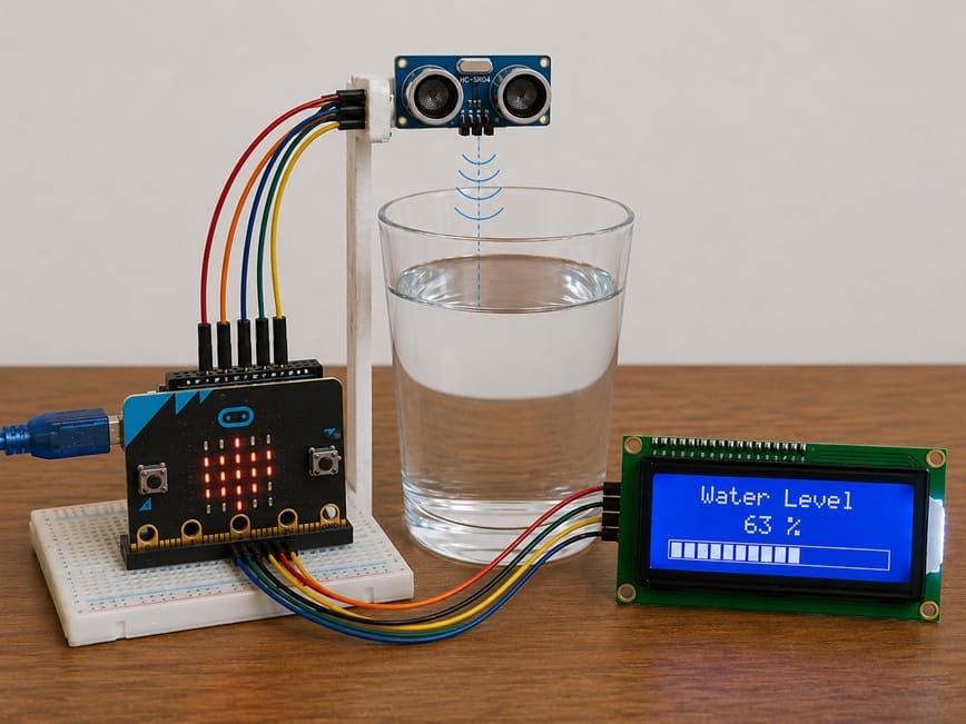
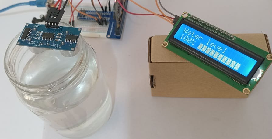
The objective of this project is to design a real-time smart water level indicator using the Micro:bit board, the HC-SR04 ultrasonic sensor, and an LCD I2C display.
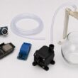
This system measures the water level inside a glass and displays the results instantly on the LCD screen using graphical bars, allowing easy and continuous monitoring of the water level.
Functioning
When water is poured into a glass, the HC-SR04 ultrasonic sensor measures the distance between the sensor and the water surface.
The Micro:bit board processes the measured distance and calculates the corresponding water level.
Then, the calculated water level is displayed on the LCD I2C screen in real time using graphic bars and percentage values.
As the water level increases, the number of displayed bars increases. Similarly, when the water level decreases, the number of displayed bars also decreases.
This smart system provides a simple and efficient solution for real-time water level monitoring.
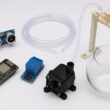
Required Components
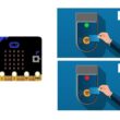
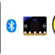
1. Micro:bit board

The Micro:bit board is the main controller of the project. It processes the data received from the ultrasonic sensor and controls the LCD display to show the water level in real time.
2. Micro:bit GPIO Extension Board

The Micro:bit GPIO extension board simplifies the connection between the Micro:bit board and external electronic components. It provides easy access to GPIO pins, power supply pins, and communication interfaces, making circuit assembly more convenient and reliable.
3. HC-SR04 sensor
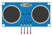
The HC-SR04 ultrasonic sensor is used to measure the distance between the sensor and the water surface inside the glass. It sends ultrasonic waves and calculates the distance according to the returned echo signal.
4. LCD Display with I2C Module

The LCD I2C display is used to show the water level information in real time. It can display percentage values and graphical bars representing the water level.
5. Jumper Wires

Jumper wires are used to establish electrical connections between the Micro:bit, the sensor, and the LCD display.
6. Breadboard
The breadboard is used to connect the electronic components without soldering. It simplifies circuit assembly and testing.
Circuit Connections of system
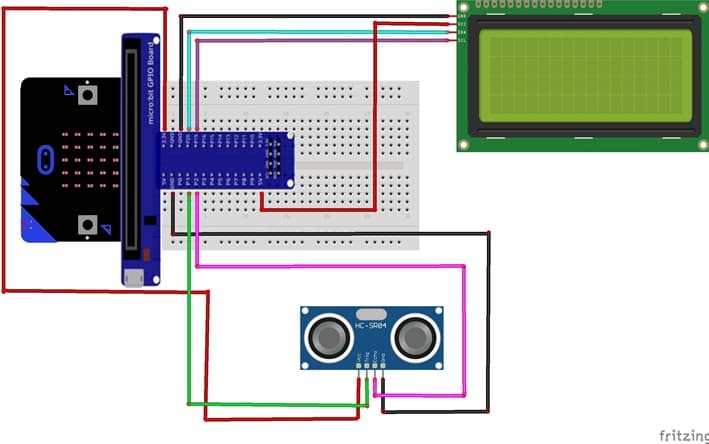
1- Connection of HC-SR04 sensor to Micro:bit
| HC-SR04 sensor | Micro:bit board |
|---|---|
| VCC | 5V (power supply) |
| GND | GND |
| Trig | P1 |
| Echo | P2 |
2- Connection of LCD I2C display to Micro:bit
| LCD I2C display | Micro:bit board |
|---|---|
| VCC | 5V (power supply) |
| GND | GND |
| SDA | P20 |
| SCL | P19 |
MicroPython code for Micro:bit board
This MicroPython program is designed to implement a smart water level monitoring system using a Micro:bit board, an HC-SR04, and an LCD I2C display.
|
1 2 3 4 5 6 7 8 9 10 11 12 13 14 15 16 17 18 19 20 21 22 23 24 25 26 27 28 29 30 31 32 33 34 35 36 37 38 39 40 41 42 43 44 45 46 47 48 49 50 51 52 53 54 55 56 57 58 59 60 61 62 63 64 65 66 67 68 69 70 71 72 73 74 75 76 77 78 79 80 81 82 83 84 85 86 87 88 89 90 91 92 93 94 95 96 97 98 99 100 101 102 103 104 105 106 107 108 109 110 111 112 113 114 115 116 117 118 119 120 121 122 123 124 125 126 127 128 129 130 131 132 133 134 135 136 137 138 139 140 141 142 143 144 145 146 147 148 149 150 151 152 153 154 155 156 157 158 159 160 161 162 163 164 165 166 167 168 169 170 171 172 173 174 175 176 177 178 179 180 181 182 183 184 185 186 187 188 189 190 191 192 193 194 195 196 197 198 199 200 201 202 203 204 205 206 207 208 209 210 211 212 213 214 215 216 217 218 219 220 221 222 223 224 225 226 227 228 229 230 231 232 233 234 235 236 237 238 239 240 241 242 243 244 245 |
# Import required libraries from microbit import * import utime # I2C address of the LCD display LCD_ADDR = 0x27 # ================================================== # LCD I2C DISPLAY CONTROL FUNCTIONS # ================================================== # Send data or command to the LCD def lcd_write(cmd, mode=0): # Upper nibble (high 4 bits) of the byte high = mode | (cmd & 0xF0) | 0x08 # Lower nibble (low 4 bits) of the byte low = mode | ((cmd << 4) & 0xF0) | 0x08 # Send data with Enable pulse (E pin toggling) i2c.write(LCD_ADDR, bytes([high | 0x04])) i2c.write(LCD_ADDR, bytes([high & ~0x04])) i2c.write(LCD_ADDR, bytes([low | 0x04])) i2c.write(LCD_ADDR, bytes([low & ~0x04])) # Send command to LCD def lcd_cmd(cmd): lcd_write(cmd, 0) # Send character/data to LCD def lcd_data(data): lcd_write(data, 1) # Initialize LCD display def lcd_init(): # Startup delay sleep(50) # LCD initialization sequence (4-bit mode) lcd_cmd(0x33) lcd_cmd(0x32) # 4-bit mode, 2 lines display lcd_cmd(0x28) # Display ON, cursor OFF lcd_cmd(0x0C) # Auto increment cursor lcd_cmd(0x06) # Clear display lcd_cmd(0x01) sleep(5) # Clear LCD screen def lcd_clear(): lcd_cmd(0x01) sleep(5) # Display a string on LCD def lcd_putstr(text): for c in text: lcd_data(ord(c)) # Move cursor to specific position (column, row) def lcd_goto(col, row): # Calculate DDRAM address addr = col + (0x40 * row) # Set cursor position lcd_cmd(0x80 | addr) # ================================================== # CUSTOM CHARACTER (GRAPH BAR LEVELS) # ================================================== # Custom bar graph patterns (0 to 5 levels) bar_chars = [ # Empty bar [0,0,0,0,0,0,0,0], # Level 1 fill [16,16,16,16,16,16,16,16], # Level 2 fill [24,24,24,24,24,24,24,24], # Level 3 fill [28,28,28,28,28,28,28,28], # Level 4 fill [30,30,30,30,30,30,30,30], # Full bar [31,31,31,31,31,31,31,31] ] # Create custom character in LCD memory def lcd_create_char(location, pattern): # Limit location to 0–7 (LCD CGRAM slots) location &= 0x7 # Set CGRAM address for custom character lcd_cmd(0x40 | (location << 3)) # Send 8-byte pattern to LCD for i in range(8): lcd_data(pattern[i]) # ================================================== # HC-SR04 ULTRASONIC SENSOR SETUP # ================================================== # Trigger pin (P1) TRIG = pin1 # Echo pin (P2) ECHO = pin2 # Maximum height of water glass (cm) MAX_HEIGHT = 6.5 # Measure distance using ultrasonic sensor def measure_distance(): # Ensure trigger is LOW TRIG.write_digital(0) utime.sleep_us(2) # Send 10µs ultrasonic pulse TRIG.write_digital(1) utime.sleep_us(10) TRIG.write_digital(0) # Wait for echo signal to start while ECHO.read_digital() == 0: start = utime.ticks_us() # Wait for echo signal to end while ECHO.read_digital() == 1: end = utime.ticks_us() # Calculate pulse duration duration = utime.ticks_diff(end, start) # Convert time to distance (cm) return (duration * 0.034) / 2 # ================================================== # INITIALIZATION # ================================================== # Initialize LCD lcd_init() # Load custom characters into LCD memory for i in range(6): lcd_create_char(i, bar_chars[i]) # Display title on first row lcd_goto(0, 0) lcd_putstr("Water level") # ================================================== # VALUE MAPPING FUNCTION # ================================================== # Map a value from one range to another def map_value(x, in_min, in_max, out_min, out_max): return int((x - in_min) * (out_max - out_min) / (in_max - in_min) + out_min) # ================================================== # MAIN LOOP # ================================================== while True: # Measure distance between sensor and water surface distance = measure_distance() # Convert distance into water level water_level = MAX_HEIGHT - (distance - 2.3) # Ensure minimum level is 0 if water_level < 0: water_level = 0 # Ensure maximum level is not exceeded if water_level > MAX_HEIGHT: water_level = MAX_HEIGHT # Convert water level to percentage percent = int((water_level / MAX_HEIGHT) * 100) # ================================================== # DISPLAY PERCENTAGE # ================================================== lcd_goto(0, 1) # Show water level percentage lcd_putstr(str(percent) + "% ") # ================================================== # DISPLAY GRAPH BAR # ================================================== # Total number of bars total_bars = 10 # Convert percentage into graphical units (0–50) filled = map_value(percent, 0, 100, 0, total_bars * 5) # Move cursor to bar display position lcd_goto(5, 1) # Display bar graph for i in range(total_bars): # Determine fill level of each bar segment level = filled - (i * 5) # Fully filled bar if level >= 5: lcd_data(5) # Partially filled bar elif level > 0: lcd_data(level) # Empty bar else: lcd_data(0) # Refresh every 500 ms sleep(500) |
How it works ?
- The HC-SR04 sensor measures the distance between the sensor and the water surface.
- The Micro:bit calculates the actual water level based on this distance.
- The water level is converted into a percentage (0% to 100%).
- The LCD I2C displays: the water level percentage and a graphical bar representation of the water level
0 comment
Leave a comment
Passion for robotics

Recent tutorials
Robotics workshop

Polpular tutorials


Making robots

Most commented tutorials


Robotic arm

Categories
Smart Home