Smart Obstacle Detection Using Arduino UNO and FC-51 Module
Tutorial plan
1- Objective of the project
2- Required Components
3- Circuit Connections of system
4- Arduino program
Objective of the project
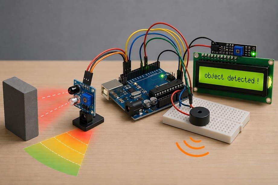
The objective of this project is to design and build a smart obstacle detection system using the Arduino UNO, the FC-51 infrared sensor, an LCD I2C display, and a buzzer. This system aims to detect the presence of nearby objects without physical contact and to provide both visual and audible feedback to the user. It helps learners understand how sensors interact with microcontrollers, how to display information in real time, and how to create simple alert systems. Such a project is useful in many applications like robotics, security systems, and automated devices.
Functioning
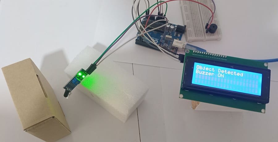
The system operates by using the FC-51 infrared sensor to continuously monitor the space in front of it. When an object comes within the sensor’s detection range, the sensor sends a digital signal to the Arduino UNO. The microcontroller processes this signal and immediately triggers two actions. First, it activates the buzzer to produce a sound alert, indicating that an obstacle has been detected. Second, it sends a message to the LCD I2C display to show information such as “Obstacle Detected” or “No Obstacle.”
When no object is present, the sensor output remains inactive, and the Arduino keeps the buzzer turned off while the LCD displays a normal status message. This continuous loop allows real-time monitoring of the environment. The use of the I2C interface simplifies the wiring of the LCD, requiring fewer pins and making the system more efficient and easier to build. Overall, the project demonstrates how different electronic components can work together to create an interactive and responsive detection system.
Required Components
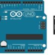
1. Arduino UNO
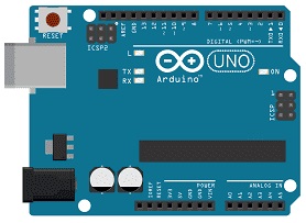
The Arduino UNO is the main microcontroller board that controls the entire system. It processes the signals received from the sensor and decides how the other components should respond. It acts as the “brain” of the project by executing the programmed instructions.
2. FC-51 sensor
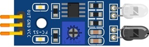
The FC-51 IR Sensor Module is used to detect obstacles. It emits infrared rays and measures the reflection from nearby objects. When an obstacle is present, the sensor sends a digital signal (HIGH or LOW) to the Arduino. It also includes a potentiometer that allows adjusting the detection sensitivity and distance.
3. LCD Display with I2C Module

The I2C LCD 16x2 Display is used to display messages such as “Object Detected”.
4. Buzzer
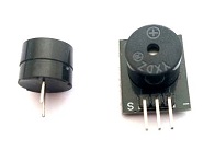
The buzzer is an output component that produces sound. In this project, it is activated when an obstacle is detected, providing an audible alert to the user. It is simple to use and requires only one control pin from the ESP32.
5. Breadboard

A breadboard is used to assemble the circuit without soldering. It makes it easy to connect and modify the components during testing and development.
6. Jumper Wires

Jumper wires are used to connect the Arduino UNO, FC-51 sensor, and LCD display together. They ensure proper electrical connections between all components.
Circuit Connections of system
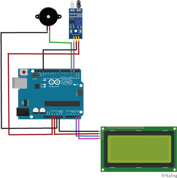
1- Connection of FC-51 sensor to Arduino UNO
| FC-51 sensor | Arduino UNO |
|---|---|
| VCC | 3V |
| GND | GND |
| OUT | D2 |
2- Connection of LCD I2C display to Arduino UNO
| LCD I2C display | Arduino UNO |
|---|---|
| VCC | 5V |
| GND | GND |
| SDA | A4 |
| SCL | A5 |
3- Connection of Buzzer to Arduino UNO
| Buzzer | Arduino UNO |
|---|---|
| Terminal (+) | D3 |
| Terminal (-) | GND |
Arduino program of system
This Arduino program implements a smart obstacle detection system using an infrared sensor, a buzzer, and an I2C LCD display. It continuously monitors the environment and provides both visual and audible feedback when an object is detected.
You need to install this library : LiquidCrystal_I2C for I2C LCD screen.
|
1 2 3 4 5 6 7 8 9 10 11 12 13 14 15 16 17 18 19 20 21 22 23 24 25 26 27 28 29 30 31 32 33 34 35 36 37 38 39 40 41 42 43 44 45 46 47 48 49 50 51 52 53 54 55 56 57 58 59 60 61 62 63 64 |
//====================================== // Object Detection with FC-51 Sensor // Arduino UNO + Buzzer + LCD I2C 20x4 //====================================== #include <Wire.h> // Library for I2C communication #include <LiquidCrystal_I2C.h> // Library for I2C LCD display // I2C address of the LCD (commonly 0x27 or 0x3F) LiquidCrystal_I2C lcd(0x27, 20, 4); // Pin definitions const int sensorPin = 2; // FC-51 sensor output pin const int buzzerPin = 3; // Buzzer control pin void setup() { pinMode(sensorPin, INPUT); // Set sensor pin as input pinMode(buzzerPin, OUTPUT); // Set buzzer pin as output lcd.init(); // Initialize the LCD lcd.backlight(); // Turn on LCD backlight // Display startup message lcd.setCursor(0,0); lcd.print(" IR Object Sensor "); lcd.setCursor(0,1); lcd.print(" System Ready... "); delay(2000); // Wait for 2 seconds lcd.clear(); // Clear the screen } void loop() { // Read the state of the sensor (LOW = object detected) int sensorState = digitalRead(sensorPin); if(sensorState == LOW) // Object detected { digitalWrite(buzzerPin, HIGH); // Turn ON buzzer // Display detection message lcd.setCursor(0,0); lcd.print("Object Detected "); lcd.setCursor(0,1); lcd.print("Buzzer ON "); } else // No object detected { digitalWrite(buzzerPin, LOW); // Turn OFF buzzer // Display no object message lcd.setCursor(0,0); lcd.print("No Object "); lcd.setCursor(0,1); lcd.print("Buzzer OFF "); } delay(200); // Small delay for stability } |
At the beginning, the program includes the necessary libraries for I2C communication and LCD control. It then initializes the LCD display (20 columns × 4 rows) and defines two pins: one connected to the FC-51 infrared sensor and the other to the buzzer. In the setup() function, the sensor pin is configured as an input and the buzzer pin as an output. The LCD is initialized, its backlight is turned on, and a welcome message (“System Ready…”) is displayed for two seconds before clearing the screen.
In the loop() function, the Arduino continuously reads the digital signal from the sensor. If an obstacle is detected (the sensor outputs a LOW signal), the program activates the buzzer and displays “Object Detected” along with “Buzzer ON” on the LCD. If no obstacle is present (HIGH signal), the buzzer is turned off and the LCD shows “No Object” and “Buzzer OFF.”
0 comment
Leave a comment
Passion for robotics

Recent tutorials


Robotics workshop

Polpular tutorials


Making robots

Most commented tutorials


Robotic arm

Categories
Smart Home