Obstacle detection with Micro:bit and FC-51 sensor
Tutorial plan
1- Objective of the project
2- Required Components
3- Circuit Connections of system
4- Makecode program of Micro:bit
Objective of the project
The objective of this project is to design and implement a simple and efficient obstacle detection system using a Micro:bit board, an FC-51 infrared sensor, an I2C LCD display, and a buzzer. The system aims to detect the presence of nearby objects and provide immediate feedback to the user through visual and audible signals. This type of project is commonly used in robotics and automation to enhance safety, avoid collisions, and improve interaction with the environment. It also helps learners understand the basics of embedded systems, sensor integration, and real-time data processing.
Functioning of the System
The system operates by continuously monitoring the environment using the FC-51 infrared sensor. When an object comes within the detection range of the sensor, it reflects the emitted infrared light back to the receiver, triggering a digital signal. The Micro:bit reads this signal and determines whether an obstacle is present or not. If an object is detected, the Micro:bit sends a command to the I2C LCD display to show a warning message, while simultaneously activating the buzzer to produce a sound alert.
If no obstacle is detected, the system remains in a standby state, displaying a normal status message on the LCD and keeping the buzzer off. This continuous loop allows the system to react instantly to any change in the environment. The combination of visual feedback (LCD) and audio alert (buzzer) ensures that the user is clearly informed of any obstacle, making the system reliable and effective for real-world applications such as smart vehicles, security systems, and assistive devices.
Required Components
1. BBC Micro:bit (Microcontroller)

The main control unit is the BBC micro:bit. It acts as the “brain” of the system by reading the signal from the sensor, processing the information, and controlling the output devices. It executes the program logic and ensures real-time interaction between all components.
2. GPIO Extension Card for Micro:bit

The GPIO extension card Expands the number of usable input/output pins on the Micro:bit, making it easier to connect multiple components.
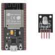
3. FC-51 sensor
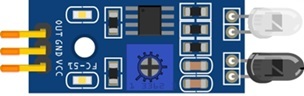
The FC-51 Infrared Obstacle Avoidance Sensor is used to detect objects. It emits infrared light and measures the reflection from nearby surfaces. When an object is detected within a certain range, the sensor outputs a digital signal (HIGH or LOW), which is sent to the Micro:bit.
4. LCD Display with I2C Module

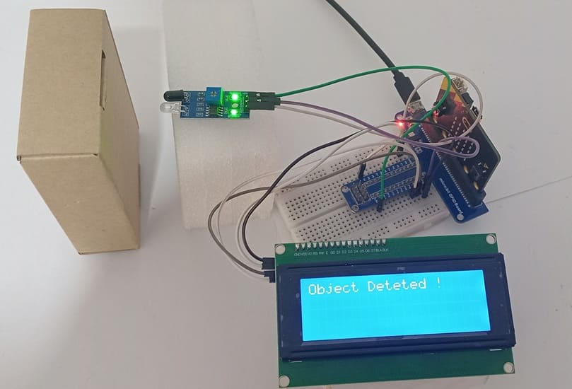
The I2C LCD 16x2 Display is used to display messages such as “Object Detected”.
5. Breadboard

A breadboard is used to assemble the circuit without soldering. It makes it easy to connect and modify the components during testing and development.
6. Jumper Wires

Jumper wires are used to connect the Micro:bit, FC-51 sensor, and LCD display together. They ensure proper electrical connections between all components.
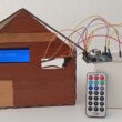
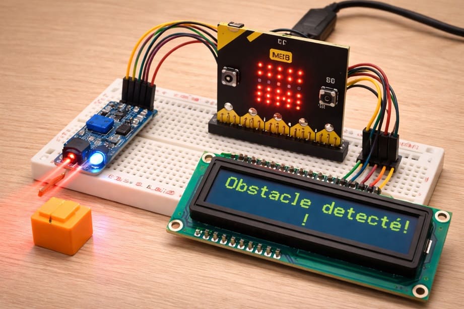
Circuit Connections of system
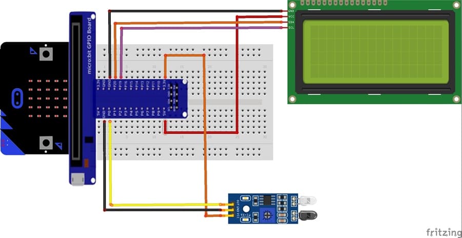
1- Connection of FC-51 sensor to Micro:bit
| FC-51 sensor | Micro:bit board |
|---|---|
| VCC | 3V |
| GND | GND |
| OUT | P0 |
2- Connection of LCD I2C display to Micro:bit
| LCD I2C display | Micro:bit board |
|---|---|
| VCC | 5V of GPIO card |
| GND | GND |
| SDA | P20 |
| SCL | P19 |
Makecode program of Micro:bit
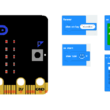
1- Open MakeCode (makecode.microbit.org).
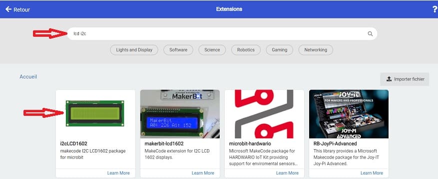
2- Click on Extensions.

3- In the search bar, type "I2C LCD," and you should find an extension for the I2C LCD display. Add it to your project.
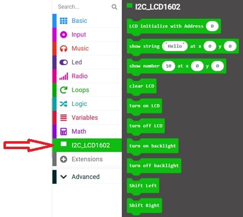
This program implements an obstacle detection system using a Micro:bit, an FC-51 infrared sensor, an I2C LCD display, and a sound alert.
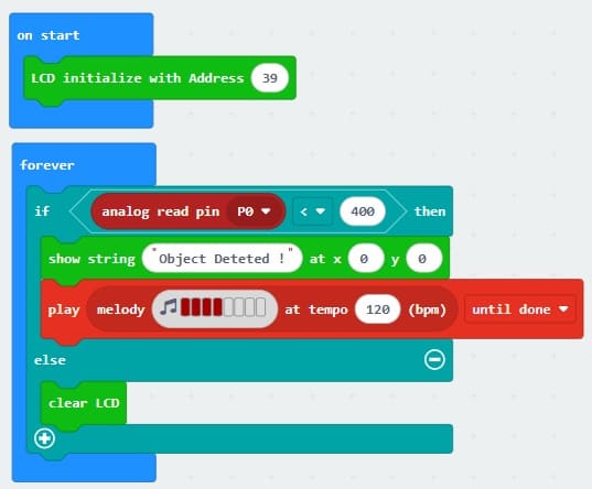
At the beginning, the instruction I2C_LCD1602.LcdInit(39) initializes the LCD display with the I2C address 0x27 (decimal 39). This allows the Micro:bit to send messages to the screen.
The program then runs continuously inside the basic.forever(function () { ... }) loop. In each cycle, the Micro:bit reads the signal coming from the FC-51 sensor through analog pin P0 using pins.analogReadPin(AnalogPin.P0).
The FC-51 sensor detects obstacles by emitting infrared light and measuring its reflection. When an object is close, the reflected signal changes, causing the sensor output value to drop below a certain threshold. In this program, the threshold is set to 400.
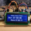
If the measured value is less than 400, the system considers that an obstacle is detected. The LCD displays the message "Object Deteted !", and the Micro:bit plays a repetitive sound (note C5), acting as an audible alarm.
If the value is greater than or equal to 400, it means no object is detected. In this case, the LCD screen is cleared, and no sound is produced.
0 comment
Leave a comment
Passion for robotics

Recent tutorials


Robotics workshop

Polpular tutorials


Making robots

Most commented tutorials


Robotic arm

Categories
Smart Home