Obstacle detection with ESP8266 NodeMCU and FC-51 sensor
Tutorial plan
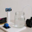
1- Objective of the project
2- Required Components
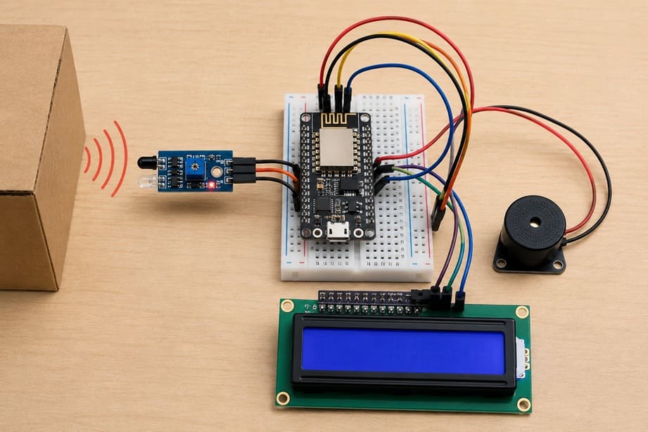
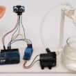
3- Circuit Connections of system
4- Micropython program of ESP8266
Objective of the project
The main objective of the Obstacle Detection System using ESP8266 NodeMCU, FC-51 infrared sensor, LCD I2C display, and buzzer is to detect the presence of an object in front of the sensor and immediately inform the user through visual and sound signals.
This type of system is commonly used in robotics and automation projects to:
- Avoid collisions in small robots or smart devices
- Monitor nearby movement or obstacles
- Display real-time detection status on an LCD screen
Provide an audible alert using a buzzer when an obstacle is detected
Functioning (How it works)
The system works by combining sensor input, microcontroller processing, and output alerts:
1- FC-51 Infrared Sensor Detection
The FC-51 sensor continuously emits infrared light and checks its reflection.
If no object is detected → normal state
If an object is detected → the reflected IR signal changes, and the sensor sends a digital signal to the ESP8266 NodeMCU
2- ESP8266 NodeMCU Processing
The NodeMCU reads the signal from the sensor and decides what action to take. It acts as the “brain” of the system.
3- LCD I2C Display Output
The LCD shows the current status:
“No Obstacle” when the path is clear
“Obstacle Detected” when an object is in front of the sensor
4- Buzzer Alert System
When an obstacle is detected, the buzzer is activated to produce a sound warning, giving an immediate alert even without looking at the screen.
Required Components
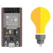
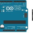
1. ESP826 NodeMCU
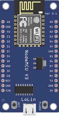
The ESP8266 NodeMCU is a Wi-Fi-enabled microcontroller board that acts as the brain of the system. It reads the signal from the IR sensor, processes the data, and controls the outputs (LCD and buzzer). It is easy to program using MicroPython and is widely used in IoT projects.
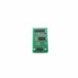
2. FC-51 sensor
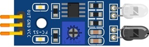
The FC-51 IR obstacle sensor is used to detect obstacles. It works by emitting infrared light and measuring the reflection. When an object is placed in front of the sensor, the reflected light is detected, and the sensor sends a digital signal to the ESP826 NodeMCU. It also includes a small potentiometer that allows adjusting the detection sensitivity.
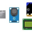
3. LCD Display with I2C Module

The I2C LCD 16x2 Display is used to display messages such as “Object Detected”.
4. Buzzer
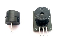
The buzzer is an output component that produces sound. In this project, it is activated when an obstacle is detected, providing an audible alert to the user. It is simple to use and requires only one control pin from the ESP8266.
5. Breadboard

A breadboard is used to assemble the circuit without soldering. It makes it easy to connect and modify the components during testing and development.
6. Jumper Wires

Jumper wires are used to connect the ESP8266 NodeMCU board, FC-51 sensor, and LCD display together. They ensure proper electrical connections between all components.
Circuit Connections of system
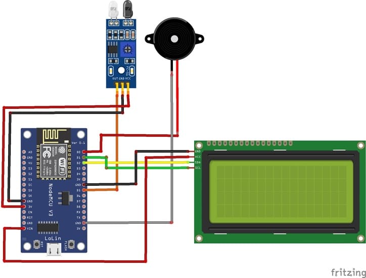
1- Connection of FC-51 sensor to ESP8266 NodeMCU
| FC-51 sensor | ESP8266 NodeMCU |
|---|---|
| VCC | 3V |
| GND | GND |
| OUT | D5 |
2- Connection of LCD I2C display to ESP8266 NodeMCU
| LCD I2C display | ESP8266 NodeMCU |
|---|---|
| VCC | 5V |
| GND | GND |
| SDA | D2 |
| SCL | D1 |
3- Connection of Buzzer to ESP8266 NodeMCU
| Buzzer | ESP8266 NodeMCU |
|---|---|
| Terminal (+) | D0 |
| Terminal (-) | GND |
Micropython program of ESP8266
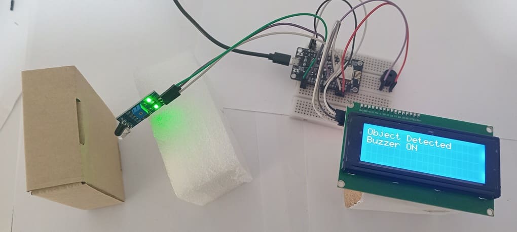
This MicroPython program is designed to implement an automatic object detection system using an ESP8266 NodeMCU, an FC-51 infrared sensor, a buzzer, and an I2C LCD display.
You need to install this libraries : i2c_lcd and lcd_api for I2C LCD screen.
|
1 2 3 4 5 6 7 8 9 10 11 12 13 14 15 16 17 18 19 20 21 22 23 24 25 26 27 28 29 30 31 32 33 34 35 36 37 38 39 40 41 42 43 44 45 46 47 48 49 50 51 52 53 54 55 56 57 58 59 60 61 62 63 64 |
# ========================================== # Object Detection using FC-51 IR Sensor # ESP8266 NodeMCU + LCD I2C 20x4 + Buzzer # ========================================== from machine import Pin, I2C from time import sleep from i2c_lcd import I2cLcd # I2C address of the LCD display (commonly 0x27 or 0x3F) I2C_ADDR = 0x27 # I2C configuration for ESP8266 # SCL -> GPIO5 (D1), SDA -> GPIO4 (D2) i2c = I2C(scl=Pin(5), sda=Pin(4), freq=400000) # Initialize LCD (4 rows, 20 columns) lcd = I2cLcd(i2c, I2C_ADDR, 4, 20) # FC-51 IR sensor connected to GPIO14 (D5) sensor = Pin(14, Pin.IN) # Buzzer connected to GPIO16 (D0) buzzer = Pin(16, Pin.OUT) buzzer.value(0) # Ensure buzzer is OFF at start # Display startup message lcd.clear() lcd.move_to(0, 0) lcd.putstr("IR Object Detector") lcd.move_to(0, 1) lcd.putstr("System Ready...") sleep(2) # Clear screen after startup lcd.clear() # Main loop while True: # Check sensor state # FC-51 outputs LOW (0) when an object is detected if sensor.value() == 0: # Object detected buzzer.value(1) # Turn ON buzzer # Display detection message on LCD lcd.move_to(0, 0) lcd.putstr("Object Detected ") lcd.move_to(0, 1) lcd.putstr("Buzzer ON ") else: # No object detected buzzer.value(0) # Turn OFF buzzer # Display safe message on LCD lcd.move_to(0, 0) lcd.putstr("No Object ") lcd.move_to(0, 1) lcd.putstr("Buzzer OFF ") # Small delay to stabilize reading sleep(0.2) |
At startup, the program initializes the I2C communication to control the 20x4 LCD screen. It then configures the hardware: the FC-51 sensor is set as an input to detect objects, and the buzzer is set as an output to generate sound alerts. A startup message is displayed on the LCD to indicate that the system is ready.
After initialization, the program enters an infinite loop where it continuously monitors the sensor state. When an object is detected (the sensor outputs LOW or 0), the buzzer is turned on and the message “Object Detected!” is displayed on the LCD. If no object is detected, the buzzer remains off and the message “No Object” is shown.
0 comment
Leave a comment
Passion for robotics

Recent tutorials

Robotics workshop

Polpular tutorials


Making robots

Most commented tutorials


Robotic arm

Categories
Smart Home