Create a Calculator with the Micro:bit Board
Tutorial plan
1- Objective of the project
2- Required Components
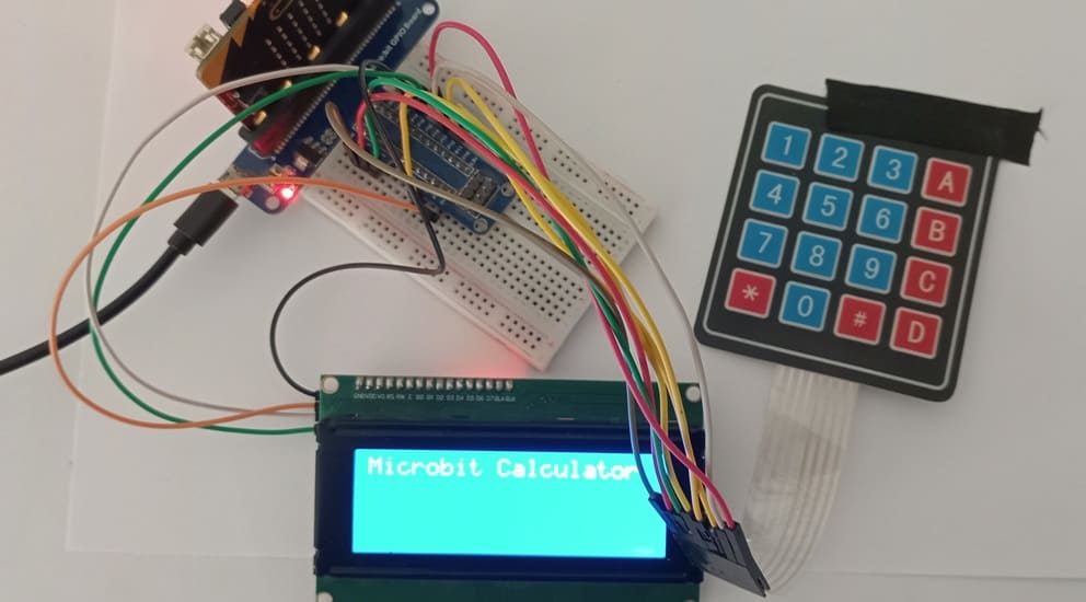
3- Circuit Connections of system
4- Micropython program of Micro:bit calculator
Objective of the project
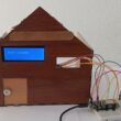
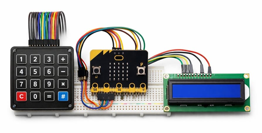
The objective of this project is to design and program a functional calculator controlled by the Micro:bit board, using an I2C LCD display for output and a 4x4 matrix keypad for user input.
This project aims to help learners understand how to interface the Micro:bit with external hardware components, including an LCD display for showing numbers and results, and a matrix keypad for entering mathematical operations. It also develops programming skills in MicroPython (or MakeCode), particularly in handling input scanning, data processing, conditional statements, and arithmetic operations.
By completing this project, students will:
Learn how to connect and configure an I2C LCD display with the Micro:bit.
Understand how a 4x4 matrix keypad works and how to read key presses.
Implement basic arithmetic operations (addition, subtraction, multiplication, and division).
Develop problem-solving skills through embedded system design.
Gain practical experience in combining hardware and software to create a real electronic device.
Overall, this project introduces fundamental concepts of embedded systems, electronics, and programming in an interactive and educational way.
Required Components
1. BBC Micro:bit (Microcontroller)

The Micro:bit is a small programmable microcontroller board designed for education. It acts as the main controller (brain) of the calculator.
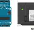
2. GPIO Extension Card for Micro:bit

The GPIO extension card Expands the number of usable input/output pins on the Micro:bit, making it easier to connect multiple components like the keypad and LCD display.
3. 4x4 Matrix Keypad
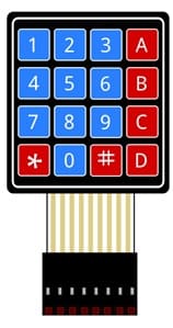
The 4x4 matrix keypad is used to input numbers and operations.
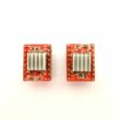
5. LCD Display with I2C Module

The LCD I2C display is used to show: entered numbers, mathematical operations and calculation results.
6. Breadboard

Breadboard is used for building a non-permanent circuit without soldering.
7. Jumper Wires

Jumper wires (male-to-male or male-to-female) are used to connect components to the Micro:bit.
Circuit Connections of system
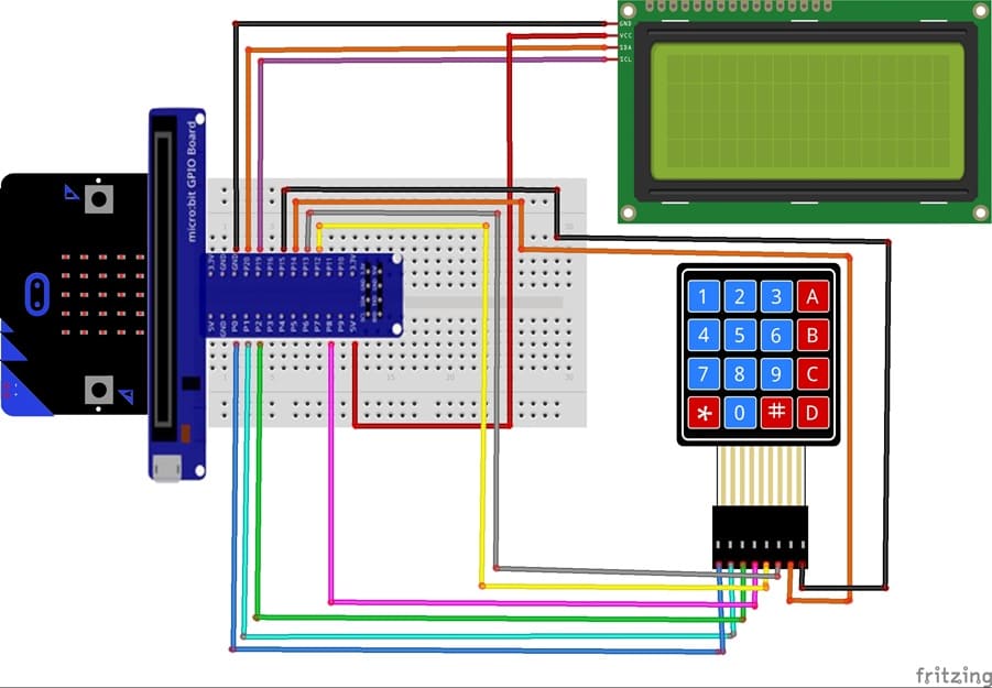
1- Connection of keypad to Micro:bit
| 4x4 Keypad | Micro:bit |
|---|---|
| R1 | P0 |
| R2 | P1 |
| R3 | P2 |
| R4 | P8 |
| C1 | P12 |
| C2 | P13 |
| C3 | P14 |
| C4 | P15 |
Connection of LCD I2C display to Micro:bit
| LCD I2C display | Micro:bit |
|---|---|
| VCC | 5V of GPIO card |
| GND | GND |
| SDA | P20 |
| SCL | P19 |
Micropython program of Micro:bit calculator
This program transforms the Micro:bit into a functional calculator using a 4x4 matrix keypad for input and an I2C LCD display for output.
You need to install this library : i2c_lcd for I2C LCD screen.
|
1 2 3 4 5 6 7 8 9 10 11 12 13 14 15 16 17 18 19 20 21 22 23 24 25 26 27 28 29 30 31 32 33 34 35 36 37 38 39 40 41 42 43 44 45 46 47 48 49 50 51 52 53 54 55 56 57 58 59 60 61 62 63 64 65 66 67 68 69 70 71 72 73 74 75 76 77 78 79 80 81 82 83 84 85 86 87 88 89 90 91 92 93 94 95 96 97 98 99 100 101 102 103 104 105 106 107 108 109 110 111 112 113 114 115 116 117 118 119 120 121 122 123 124 125 126 127 128 129 130 131 132 133 134 135 136 137 138 139 140 141 142 143 144 145 146 147 148 |
from microbit import * from i2c_lcd import I2cLcd # ---------- LCD Initialization ---------- # Create an LCD object: # i2c -> Micro:bit I2C communication # 0x27 -> I2C address of the LCD (may vary: 0x27 or 0x3F) # 4 -> Number of rows # 20 -> Number of columns lcd = I2cLcd(i2c, 0x27, 4, 20) # Clear the LCD screen lcd.clear() # Display welcome message lcd.putstr("Microbit Calculator") sleep(2000) # Wait 2 seconds lcd.clear() # ---------- Keypad Configuration ---------- # Define row pins lignes = [pin0, pin1, pin2, pin8] # Define column pins colonnes = [pin12, pin13, pin14, pin15] # Define keypad layout (4x4 matrix) touches = [ ['1','2','3','+'], ['4','5','6','-'], ['7','8','9','*'], ['=','0','#','/'] ] # Set all row pins as outputs and keep them HIGH (inactive state) for l in lignes: l.write_digital(1) # Set all column pins as inputs with internal pull-up resistors for c in colonnes: c.set_pull(c.PULL_UP) # ---------- Function to Read Pressed Key ---------- def lire_touche(): # Scan each row for i in range(4): lignes[i].write_digital(0) # Activate one row (set LOW) # Check each column for j in range(4): # If a column reads LOW, a key is pressed if colonnes[j].read_digital() == 0: sleep(300) # Debounce delay lignes[i].write_digital(1) # Reset row return touches[i][j] # Return pressed key lignes[i].write_digital(1) # Reset row after checking return None # No key pressed # ---------- Calculation Function ---------- def calculer(expr): # Lists to store numbers and operators nombres = [] ops = [] temp = "" # Separate numbers and operators from the expression for c in expr: if c.isdigit(): temp += c # Build multi-digit number else: nombres.append(float(temp)) ops.append(c) temp = "" # Add the last number nombres.append(float(temp)) # First handle multiplication (*) and division (/) i = 0 while i < len(ops): if ops[i] == '*' or ops[i] == '/': if ops[i] == '*': res = nombres[i] * nombres[i+1] else: res = nombres[i] / nombres[i+1] # Replace the two numbers with the result nombres[i] = res nombres.pop(i+1) ops.pop(i) else: i += 1 # Then handle addition (+) and subtraction (-) resultat = nombres[0] for i in range(len(ops)): if ops[i] == '+': resultat += nombres[i+1] elif ops[i] == '-': resultat -= nombres[i+1] return resultat # ---------- Main Program ---------- expression = "" # Stores the current expression while True: touche = lire_touche() # Read pressed key if touche: # Clear expression if 'C' is pressed if touche == 'C': expression = "" lcd.clear() # If '=' is pressed, calculate result elif touche == '=': if expression != "": try: res = calculer(expression) # Display result on third row lcd.move_to(0, 2) lcd.putstr("= " + str(res)) sleep(4000) lcd.clear() except: # Display error message if calculation fails lcd.clear() lcd.putstr("Erreur") expression = "" # Otherwise, add pressed key to expression else: expression += touche # Clear first row before displaying new expression lcd.move_to(0, 0) lcd.putstr(" " * 20) lcd.move_to(0, 0) lcd.putstr(expression) |
0 comment
Leave a comment
Passion for robotics

Recent tutorials


Robotics workshop

Polpular tutorials


Making robots

Most commented tutorials


Robotic arm

Categories
Smart Home