Implementation of gas leak detection system using ESP8266 NodeMCU and MQ-4

Tutorial plan
1- Objective of the tutorial
2- Operation of the gas leak detection system
3- The necessary components
4- System wiring diagram
5- Program ESP8266 NodeMCU with MicroPython
Objective of the tutorial
The objective of this tutorial is to design and implement a gas leak detection system using the ESP8266 NodeMCU microcontroller and the MQ-4 gas sensor.
This system aims to detect the presence of flammable gases such as methane (CH₄) and butane in the surrounding environment. When the gas concentration exceeds a predefined safety threshold, the system triggers visual and audible alerts to warn users of a potential leak.
Through this tutorial, you will learn how to:
- interface the MQ-4 gas sensor with the ESP8266 NodeMCU.
- read and process the analog data from the sensor.
- display real-time gas concentration levels on an I2C LCD screen.
- activate a buzzer and LED indicator when a gas leak is detected.
Ultimately, this project demonstrates how IoT-based embedded systems can be applied to enhance safety and prevent accidents caused by gas leaks in residential or industrial environments.
Operation of the gas leak detection system
The gas leak detection system operates based on the principle of monitoring the concentration of combustible gases (such as methane, butane, and propane) in the surrounding environment using the MQ-4 gas sensor.
The MQ-4 sensor contains a sensitive material (tin dioxide, SnO₂) whose resistance decreases when it comes into contact with flammable gases. This change in resistance produces a variation in the output voltage, which is proportional to the concentration of gas in the air.
The ESP8266 NodeMCU reads this analog voltage signal through its A0 input pin and converts it into a digital value that represents the gas concentration level. The microcontroller then compares this value with a predefined safety threshold.
If the gas concentration is below the threshold:
1- the environment is considered safe.
2- the LED remains off.
3- the buzzer is silent.
If the gas concentration exceeds the threshold:
1- the system detects a gas leak.
2- the LED turns on to provide a visual warning.
3- the buzzer activates to generate an audible alarm.
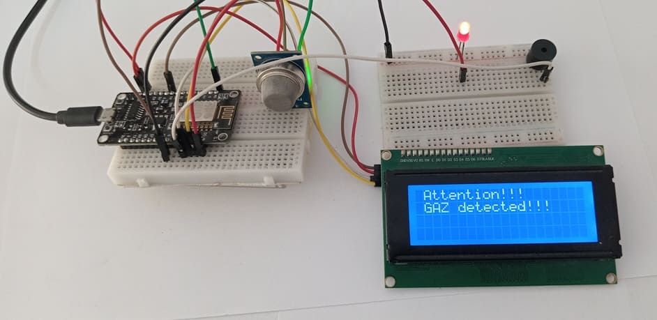
4- the I2C LCD screen displays an alert message like “Gas Detected!” along with the real-time sensor value.
This operation ensures that any increase in gas concentration is detected immediately, allowing users to take quick action to prevent fire, explosion, or poisoning.
The necessary components
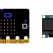
1- ESP8266 NodeMCU Board
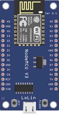
The ESP8266 NodeMCU Board serves as the main microcontroller that reads the gas sensor data, processes it, and controls the output devices (LED, buzzer, LCD).
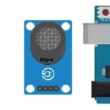
2- MQ-4 Gas Sensor

The MQ-4 Gas Sensor detects the presence of combustible gases such as methane (CH₄), butane, or propane in the air and outputs an analog signal proportional to the gas concentration.
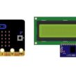
3- I2C LCD Display (20x4)
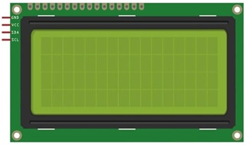
The I2C LCD screen displays real-time gas concentration values and system status messages such as “No Gas Leak” or “Gas Leak Detected”.
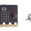
4- Buzzer

The Buzzer produces an audible alarm when the gas concentration exceeds the safety threshold.
5- LED (Red)
![]()
The LED acts as a visual indicator to alert the user of a detected gas leak.
6- Breadboard (Prototype Board)
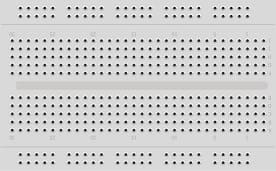
The Breadboard is used for assembling and testing the circuit without soldering.
7- Jumper Wires
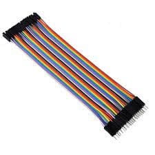
The jumper wires Connect all components together on the breadboard.
System wiring diagram
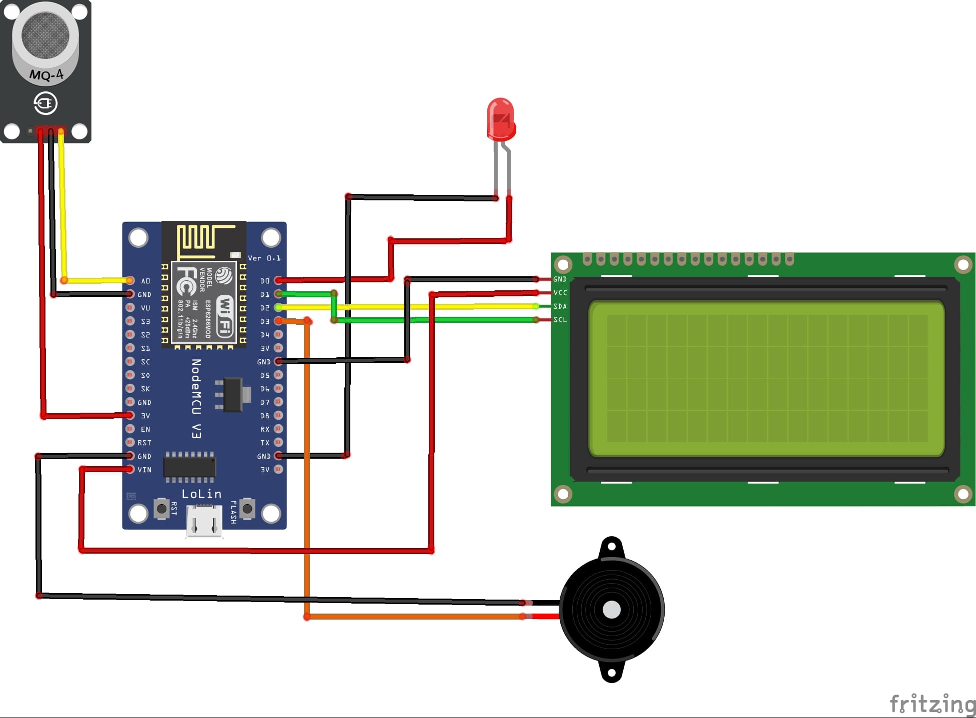
Attaching the I2C LCD Display :
- connect the VCC pin of the display to 5V pin of the ESP8266
- connect the GND pin of the display to GND pin of the ESP8266
- connect the SDA pin of the display to D2 (GPIO4) pin of the ESP8266
- connect the SCL pin of the display to D1 (GPIO5) pin of the ESP8266
Attaching the MQ-4 Sensor :
- Connect DO pin of the gas sensor to A0 pin of the ESP8266 board
- Connect the VCC (+) pin of the gas sensor to the VIN (5V) pin of the ESP8266 board
- Connect the GND(-) pin of the gas sensor to the GND pin of the ESP8266 board
Attaching the red LED :
- Connect the negative terminal (cathode) of each LED to the ground (GND) of the ESP8266 board.
- Connect the positive terminal (anode) of the LED to the D0 (GPIO16) pin of the ESP8266 board.
Attaching the buzzer :
- Connect the (+) terminal of buzzer to D3 (GPIO0) pin on the ESP8266 board.
- Connect the (-) terminal of buzzer to GND pin on the ESP8266 board.
Program ESP8266 NodeMCU with MicroPython
To program the gas leak detection system using ESP8266 NodeMCU, you'll need to follow these steps.
1- import this two libraries : i2c_lcd and lcd_api for I2C LCD screen
2- Create a new Python script and write the following code :
|
1 2 3 4 5 6 7 8 9 10 11 12 13 14 15 16 17 18 19 20 21 22 23 24 25 26 27 28 29 30 31 32 33 34 35 36 37 |
from machine import Pin, SoftI2C , ADC from lcd_api import LcdApi from i2c_lcd import I2cLcd from time import sleep I2C_ADDR = 0x27 totalRows = 4 totalColumns = 20 # Configure I2C for LCD screen i2c = SoftI2C(scl=Pin(5), sda=Pin(4), freq=10000) lcd = I2cLcd(i2c, I2C_ADDR, totalRows, totalColumns) # Configure led, buzzer and mq4 sensor pins redled_pin=Pin(16, Pin.OUT) buzzer_pin=Pin(0, Pin.OUT) mq4_pin = ADC(0) while True: mq4_value = mq4_pin.read() # Reading the analog value returned by the sensor if (mq4_value<200): # When a gas leak is detected # Activate buzzer and LED redled_pin.value(1) buzzer_pin.value(1) # show alert message on LCD I2C display lcd.move_to(1,0) lcd.putstr("Attention!!!") lcd.move_to(1,1) lcd.putstr("GAS detected!!!") else: # Disable buzzer and LED redled_pin.value(0) buzzer_pin.value(0) lcd.clear() sleep(0.1) |
Explanation :
- The analog value gives the intensity of the das.
- The digital output (DO) becomes LOW when a flame is detected.
- The LCD displays alert message ("Gas detected").
- The LED and Buzzer are activated when a gasleak is detected.
0 comment
Leave a comment
Passion for robotics

Recent tutorials


Robotics workshop

Polpular tutorials


Making robots

Most commented tutorials


Robotic arm

Categories
Smart Home