Micro:bit Alarm Clock with DS1302 RTC Module
Tutorial plan
1- Objective of the project
2- Required Components
3- Circuit Connections of system
4- Makecode program of Micro:bit Alarm Clock
Objective of the project
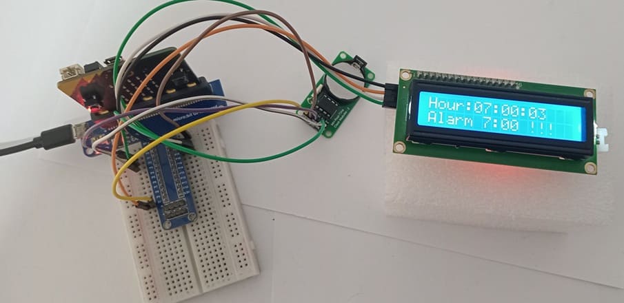
The objective of this project is to design and implement a complete digital alarm clock system using the BBC micro:bit Foundation micro:bit, a DS1302 Real-Time Clock (RTC) module, an LCD I2C display, and the internal buzzer of the micro:bit. The system is able to display the current time accurately and activate an audible alarm using the built-in buzzer when the preset alarm time is reached.
This project helps learners understand important embedded systems concepts such as real-time clock management, time comparison, LCD display control, and sound generation using the micro:bit internal buzzer. It also demonstrates how multiple hardware components can work together to create a practical and interactive electronic device.
Functioning of the Project
The system operates by continuously reading the current time from the DS1302 RTC module and displaying it on the LCD I2C screen, while monitoring the alarm condition.
The functioning steps are as follows:
1. When the system starts, the micro:bit initializes the DS1302 RTC module and the LCD I2C display.
2. The RTC module keeps track of the current time (hours, minutes, and seconds) using its internal clock and backup battery, ensuring accurate timekeeping even when the micro:bit is powered off.
3. The micro:bit reads the current time from the RTC module at regular intervals.
4. The current time is formatted and displayed clearly on the LCD I2C display.
5. The micro:bit compares the current time with the preset alarm time stored in the program.
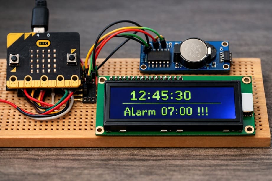
6- When the current time matches the alarm time (for example, 07:00), the system performs the following actions:
- Displays the message "Alarm 07:00 !!!" on the LCD screen
- Activates the internal buzzer of the micro:bit to generate a sound alert
- The buzzer produces a tone or repeated beeps to notify the user
7- The alarm continues for a defined duration or until the program stops it.
This cycle repeats continuously, allowing the system to function as a reliable digital alarm clock with both visual and sound alerts.
Required Components
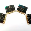
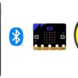
1. BBC Micro:bit (Microcontroller)

The micro:bit is a compact and programmable microcontroller board designed for education and embedded systems projects. It acts as the main controller of the alarm clock system.
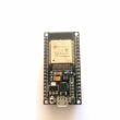
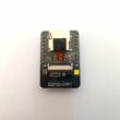
2. GPIO Extension Card for Micro:bit

The GPIO extension card Expands the number of usable input/output pins on the Micro:bit, making it easier to connect multiple components like the DS1302 RTC Module and LCD display.
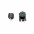
3. DS1302 RTC Module
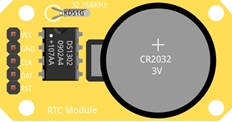
The DS1302 RTC (Real Time Clock) module is an electronic component used to keep track of the current time and date in real time. It continues to operate even when the main power is turned off, thanks to its backup battery.
5. LCD Display with I2C Module

The LCD I2C display is used to show information visually in the project. It shows the current time and alarm messages.
6. Breadboard

Breadboard is used for building a non-permanent circuit without soldering.
7. Jumper Wires

Jumper wires (male-to-male or male-to-female) are used to connect components to the Micro:bit.
Circuit Connections of system
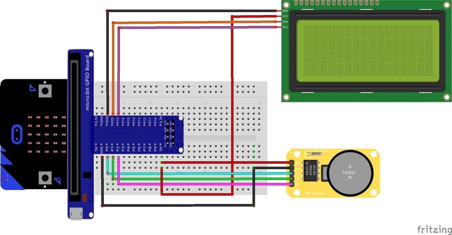
1- Connection of DS1302 RTC Module to Micro:bit
| DS1302 RTC Module | Micro:bit |
|---|---|
| CLK | P0 |
| DAT | P1 |
| RST | P2 |
| VCC | 5V of GPIO card |
| GND | GND |
2- Connection of LCD I2C display to Micro:bit
| LCD I2C display | Micro:bit |
|---|---|
| VCC | 5V of GPIO card |
| GND | GND |
| SDA | P20 |
| SCL | P19 |
Makecode program of Micro:bit Alarm Clock
1- Open MakeCode (makecode.microbit.org).
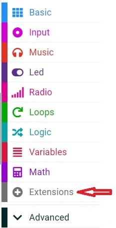
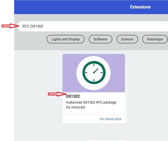
2- Click on Extensions.
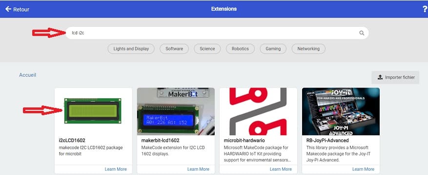
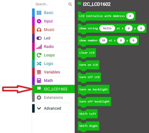
3- In the search bar, type "I2C LCD," and you should find an extension for the I2C LCD display. Add it to your project.
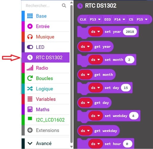
4- In the search bar, type "RTC DS1302" and you should find an extension for RTC DS1302 module. Add it to your project.
This MakeCode program creates a digital alarm clock system using the BBC micro:bit Foundation micro:bit, a DS1302 Real-Time Clock module, and an LCD I2C display. The system continuously displays the current time and activates an alarm with sound at 7:00:00.
Explanation of the MakeCode Program
1. Variable Declaration
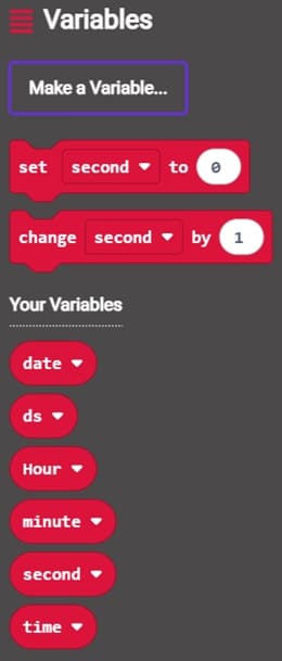
These variables are used to store:
date → stores the current date
Hour → stores the hour
minute → stores the minute
second → stores the second
time → stores the complete formatted time
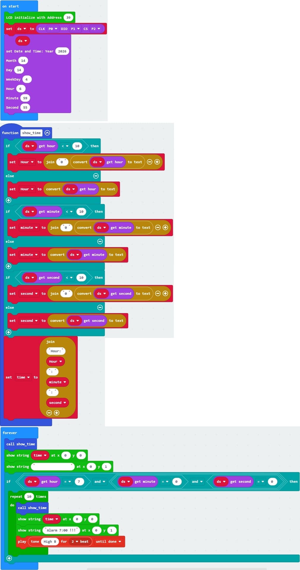
2. LCD Initialization
![]()
This instruction initializes the LCD I2C display.
3. RTC Module Initialization

This line creates the RTC object named ds.
Pins used:
P0 → CLK (Clock)
P1 → DAT (Data)
P2 → RST (Reset)
These pins allow communication between the Micro:bit and the RTC module.
4. Setting Initial Date and Time
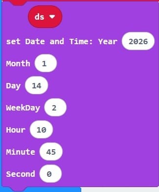
This sets the initial date and time:
Year → 2026
Month → 1
Day → 14
Hour → 2
Minute → 10
Second → 45
Day of week → 0
This step is usually done once to initialize the RTC.
5. Function show_time()
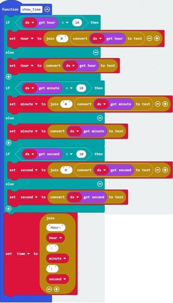
The function show_time() is responsible for reading and formatting the current time from the DS1302 RTC module.
6. Main Loop (basic.forever)
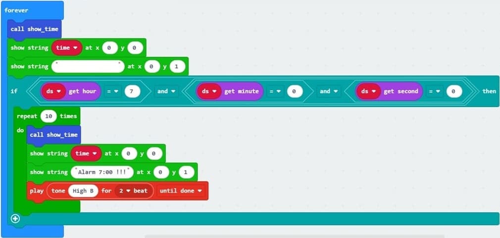
The basic.forever() block runs continuously.
It Calls show_time(), displays the current time on the first row of the LCD and clears the second row.
0 comment
Leave a comment
Passion for robotics

Recent tutorials

Robotics workshop

Polpular tutorials


Making robots

Most commented tutorials


Robotic arm

Categories
Smart Home