Bluetooth servo motor control using Micro:bit and Smartphone
Tutorial plan
1- Objective of the project
2- Required Components
3- Circuit Connections of system
4- Makecode program for Micro:bit board
5- The mobile app for controlling the servo motor
Objective of the project
The objective of this project is to control the position of a servo motor wirelessly using a smartphone and a Micro:bit board through a Bluetooth connection. The user adjusts the desired servo angle from a mobile application developed with MIT App Inventor. The command is transmitted to the Micro:bit, which processes it and controls the servo motor through a GPIO Expansion Board, enabling smooth and precise positioning in real time.
How It Works ?
1- The user moves a slider in the mobile application created with MIT App Inventor to select the desired angle of the servo motor.
2- The smartphone sends the selected angle to the Micro:bit via Bluetooth Low Energy (BLE).
3- A MakeCode program running on the Micro:bit receives the Bluetooth data through the UART service.
4- The Micro:bit converts the received value into a servo angle and sends the corresponding PWM control signal to the servo motor through the GPIO Expansion Board.
5- The GPIO Expansion Board provides a convenient interface for connecting and powering the servo motor while transmitting the PWM signal generated by the Micro:bit.
6- The servo motor rotates to the requested angle, allowing accurate and real-time wireless control from the smartphone.
Required Components
1. Micro:bit board
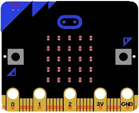
The Micro:bit is a compact programmable microcontroller board that serves as the main controller of the system. It receives Bluetooth commands from the smartphone, processes the received data, and generates the PWM signal required to control the servo motor.
2. GPIO Expansion Board
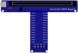
The GPIO Expansion Board extends the Micro:bit's input/output capabilities by providing convenient connectors for external devices. It simplifies the connection of the servo motor and supplies the required power while routing the control signal from the Micro:bit.
3. Servo Motor
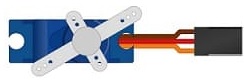
The servo motor is an actuator that rotates its shaft to a specific angle based on the PWM signal generated by the Micro:bit. It provides precise angular positioning, typically from 0° to 180°, making it suitable for robotics and automation projects.
4. Jumper Wires
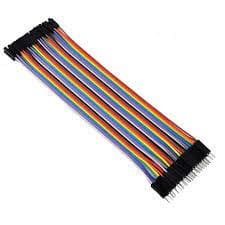
Jumper wires are used to make the electrical connections between the Micro:bit, the GPIO expansion board and the servo motor.
5. Breadboard
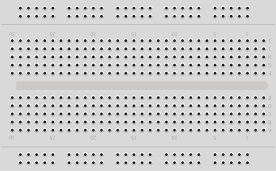
The breadboard is a solderless prototyping board used to build and test electronic circuits quickly and easily.
Circuit Connections of system
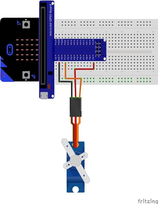
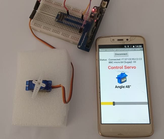
1- Connect the servo motor's signal wire (usually yellow or orange) to pin P1 of the Micro:bit board.
2- Connect the servo motor's power supply wire (VCC), usually red, to the 5V pin of the GPIO Expansion Board.
3- Connect the servo motor's ground wire (GND), usually black or brown, to a GND pin on the Micro:bit board.
MakeCode Program for the Micro:bit Board
1- Go to Microsoft MakeCode and start a new project.
2- In MakeCode, open the Blocks Editor (https://makecode.microbit.org/).
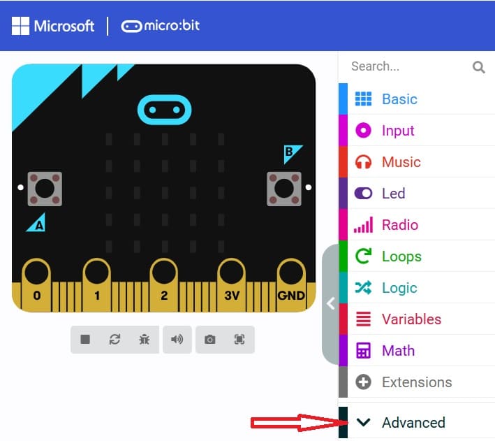
3- Go to advanced :
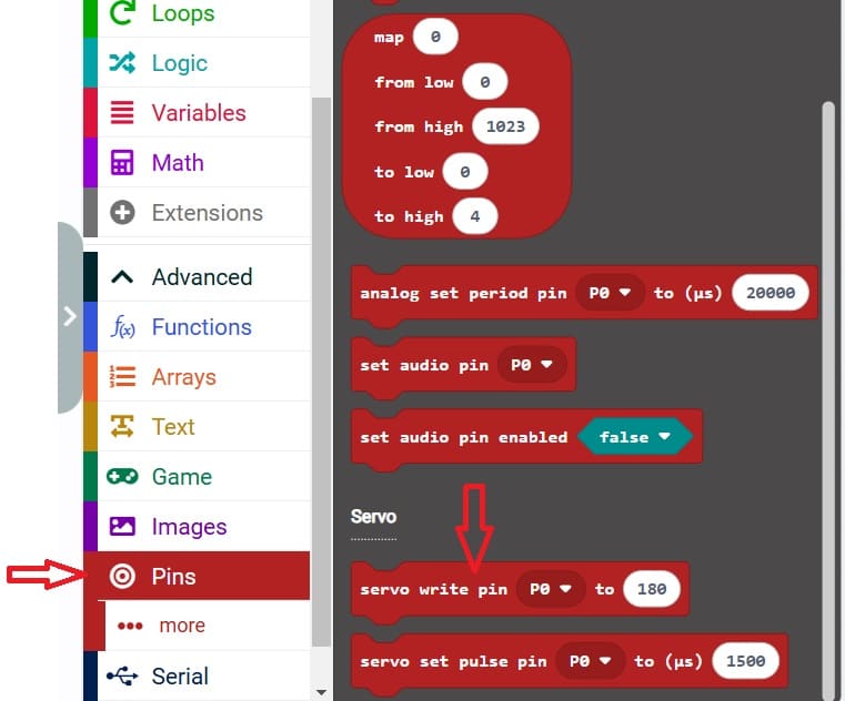
4- Go to Pin and choose 'servo write pinP0 to 180' instruction :
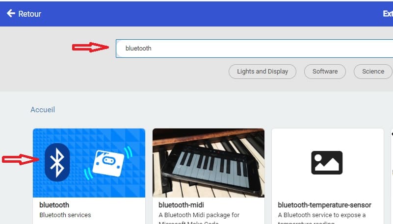
5- Add Bluetooth Extension:
Click on the "Extensions" option in the bottom left corner.
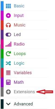
Search and add the "Bluetooth" extension by clicking on it.
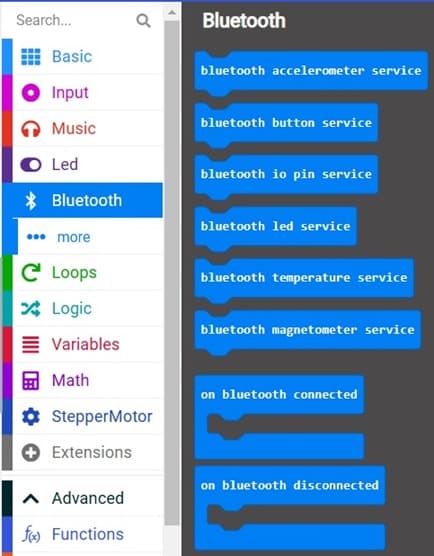
This MakeCode program allows the Micro:bit to control a servo motor wirelessly via Bluetooth using commands received from a smartphone application. It initializes Bluetooth communication, receives the desired servo angle through the UART service, and adjusts the servo position accordingly.
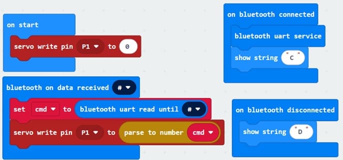
Explanation of the program
Motor Initialization
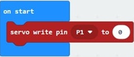
At startup, the servo motor is positioned at 0°
Bluetooth Connection
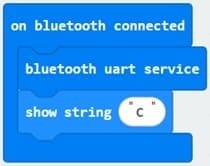
The program begins by monitoring the Bluetooth connection status. When a smartphone successfully connects to the Micro:bit, the UART (Universal Asynchronous Receiver/Transmitter) service is started using bluetooth.startUartService(). This service allows data to be exchanged between the smartphone and the Micro:bit. The letter "C" is displayed on the Micro:bit's LED matrix to indicate that the Bluetooth connection has been established successfully.
Bluetooth Disconnection
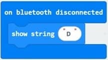
If the Bluetooth connection is interrupted, the program automatically detects the disconnection event and displays the letter "D" on the LED matrix. This provides a visual indication that communication with the smartphone has been lost.
Receiving Servo Angle Commands

The Micro:bit continuously listens for data sent by the smartphone through the Bluetooth UART service. Each message is terminated by the '#' character, which acts as the end-of-message delimiter.
The received command is stored in the variable cmd.

The received text value is converted into a numerical value.
This value represents the desired servo angle.
The Micro:bit generates a PWM signal on pin P1
The servo motor moves to the requested angle.
The mobile app for controlling the servo motor
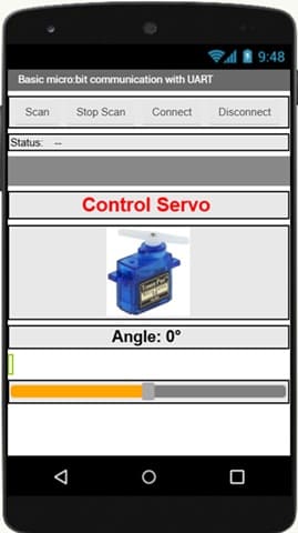
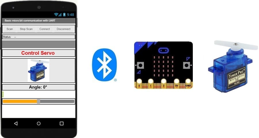
The mobile application shown in the image is designed to control a servo motor wirelessly using a smartphone and a Micro:bit through Bluetooth communication.
Application Functions
1. Bluetooth Device Management
The application provides buttons to:
Scan: Search for available Bluetooth devices.
Stop Scan: Stop the Bluetooth search process.
Connect: Establish a Bluetooth connection with the Micro:bit.
Disconnect: Close the Bluetooth communication.
2. Communication Status Display
The Status field indicates the current Bluetooth connection state between the smartphone and the Micro:bit.
3. Servo Motor Control Interface
The application displays a servo motor image to represent the controlled actuator.
A slider (SeekBar) allows the user to adjust the desired servo angle.
4. Angle Display
The application shows the selected angle value (for example, Angle: 0°).
When the slider position changes, the application updates the angle value in real time.
5. Command Transmission
The selected angle is sent from the smartphone to the Micro:bit via the Bluetooth UART service.
The Micro:bit receives this value and generates the PWM signal needed to rotate the servo motor to the requested position.
0 comment
Leave a comment
Passion for robotics

Recent tutorials
Robotics workshop
Polpular tutorials
Making robots

Most commented tutorials

Robotic arm

Categories
Smart Home