DIY vehicle speed radar using Arduino and HC-SR04 sensor
Tutorial plan
1- Objective of the project
2- Required Components
3- Circuit Connections of system
4- Arduino program
Objective of the project
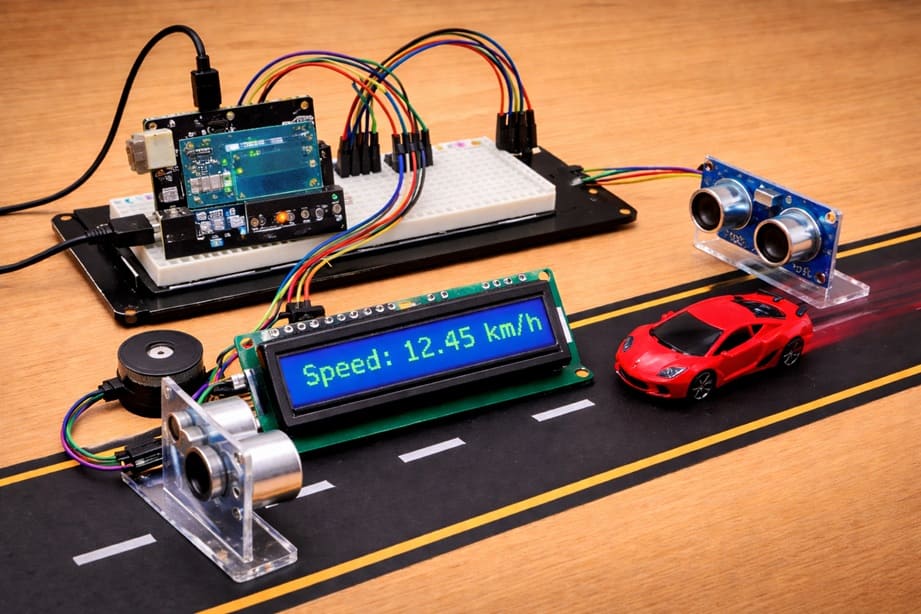
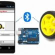
The objective of this project is to design and build a low-cost vehicle speed radar system using an Arduino UNO. By using two HC-SR04 ultrasonic sensors, the system measures the speed of a moving vehicle over a known distance.
The measured speed is then displayed in real time on an I2C LCD screen. Additionally, a buzzer is used to provide an audible alert when the detected speed exceeds a predefined safety limit.
This project demonstrates the practical application of distance measurement, time calculation, and embedded system control in traffic monitoring.
Functioning:
The system operates by placing two HC-SR04 sensors at a fixed and known distance from each other. When a vehicle passes in front of the first sensor, the Arduino detects its presence and starts a timer.
As the vehicle continues moving and reaches the second sensor, the Arduino stops the timer. Using the recorded time and the known distance between the sensors, the speed is calculated using the basic formula:
Speed = Distance / Time
The calculated speed is then displayed on the LCD I2C screen in an easy-to-read format. If the speed exceeds a predefined threshold, the buzzer is activated to alert the user.
This setup allows real-time monitoring of vehicle speed in a simple, efficient, and cost-effective way.
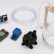
Required Components
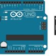
1. Arduino UNO
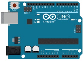
The Arduino UNO is the main control unit of the system. It processes data received from the ultrasonic sensors, calculates the vehicle speed, and controls the LCD display and buzzer. It is based on the ATmega328P microcontroller and is easy to program using the Arduino IDE.
2. HC-SR04 sensor
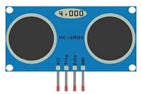
These sensors are used to detect the presence of a vehicle and measure distance. Each HC-SR04 works by sending ultrasonic waves and measuring the time it takes for the echo to return. In this project, two sensors are placed a fixed distance apart to calculate the time taken by a vehicle to travel between them.
3- Buzzer :
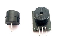
The buzzer provides an audible alert when the vehicle speed exceeds a predefined limit. It helps in making the system more interactive and useful for warning purposes.
4. LCD Display with I2C Module

The I2C LCD screen is used to display real-time information such as the measured speed, system status, and warning messages.
5. Breadboard

A breadboard is used to assemble the circuit without soldering. It makes it easy to connect and modify the components during testing and development.
6. Jumper Wires

Jumper wires are used to connect all the components together on the Arduino and breadboard. They ensure proper electrical connections between sensors, display, and other modules.
Circuit Connections of system
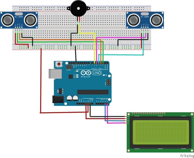
1- Connecting the first HC-SR04 sensor to the Arduino UNO
| HC-SR04 | Arduino UNO |
|---|---|
| VCC | 3 V |
| Trig | D2 |
| Echo | D3 |
| GND | GND |
2- Connecting the second HC-SR04 sensor to the Arduino UNO
| HC-SR04 | Arduino UNO |
|---|---|
| VCC | 3 V |
| Trig | D4 |
| Echo | D5 |
| GND | GND |
3- Connecting the Buzzer to the Arduino UNO
| Buzzer | Arduino UNO |
|---|---|
| (+) Terminal | D6 |
| (-) Terminal | GND |
4- Connection of LCD I2C display to Arduino UNO
| LCD I2C display | Arduino UNO |
|---|---|
| VCC | 5V of GPIO card |
| GND | GND |
| SDA | A4 |
| SCL | A5 |
Arduino program:
This program implements a vehicle speed radar system using an Arduino UNO, two HC-SR04 Ultrasonic Sensor sensors, an I2C LCD Display, and a Buzzer. Its main purpose is to measure the speed of a moving object (such as a vehicle) and alert the user if the speed exceeds a predefined limit.
You need to install this libraries : LiquidCrystal_I2C for I2C LCD screen
|
1 2 3 4 5 6 7 8 9 10 11 12 13 14 15 16 17 18 19 20 21 22 23 24 25 26 27 28 29 30 31 32 33 34 35 36 37 38 39 40 41 42 43 44 45 46 47 48 49 50 51 52 53 54 55 56 57 58 59 60 61 62 63 64 65 66 67 68 69 70 71 72 73 74 75 76 77 78 79 80 81 82 83 84 85 86 87 88 89 90 91 92 93 94 95 96 97 98 99 100 101 102 103 104 105 106 107 108 109 110 111 112 113 114 115 116 117 118 119 120 121 122 123 124 125 126 127 128 129 130 131 132 133 134 135 136 137 138 139 140 141 142 143 144 145 146 147 148 149 150 151 152 153 154 155 156 157 158 159 160 161 162 163 164 165 166 167 168 169 170 171 172 173 174 175 176 177 178 |
#include <Wire.h> #include <LiquidCrystal_I2C.h> // ========================= // CONFIGURATION // ========================= // Distance between the two sensors (in meters) #define DISTANCE 0.10 // Distance threshold (in cm) to detect an object #define DETECTION_THRESHOLD 5 // Speed limit (in km/h) for triggering the buzzer #define SPEED_LIMIT 1.0 // Sensor 1 pins #define TRIG1 2 #define ECHO1 3 // Sensor 2 pins #define TRIG2 4 #define ECHO2 5 // Buzzer pin #define BUZZER 6 // Initialize I2C LCD (address 0x27, 20 columns, 4 rows) LiquidCrystal_I2C lcd(0x27, 20, 4); // ========================= // FUNCTIONS // ========================= // Function to measure distance using HC-SR04 (returns distance in cm) float measureDistance(int trig, int echo) { digitalWrite(trig, LOW); // Ensure trigger is LOW delayMicroseconds(2); digitalWrite(trig, HIGH); // Send 10µs pulse to trigger delayMicroseconds(10); digitalWrite(trig, LOW); // Measure the duration of the echo pulse (timeout: 30ms) long duration = pulseIn(echo, HIGH, 30000); // If no signal is received, return -1 (error) if (duration == 0) return -1; // Convert time to distance (speed of sound = 0.0343 cm/µs) return (duration * 0.0343) / 2; } // Function to detect if an object is within the threshold distance bool objectDetected(int trig, int echo) { float d = measureDistance(trig, echo); return (d > 0 && d < DETECTION_THRESHOLD); } // Function to display 4 lines on the LCD void displayLCD(String l1 = "", String l2 = "", String l3 = "", String l4 = "") { lcd.clear(); // Clear previous display lcd.setCursor(0, 0); lcd.print(l1); lcd.setCursor(0, 1); lcd.print(l2); lcd.setCursor(0, 2); lcd.print(l3); lcd.setCursor(0, 3); lcd.print(l4); } // Function to activate the buzzer for a given duration (ms) void beep(int duration = 200) { digitalWrite(BUZZER, HIGH); // Turn buzzer ON delay(duration); digitalWrite(BUZZER, LOW); // Turn buzzer OFF } // ========================= // INITIALIZATION // ========================= void setup() { // Configure sensor pins pinMode(TRIG1, OUTPUT); pinMode(ECHO1, INPUT); pinMode(TRIG2, OUTPUT); pinMode(ECHO2, INPUT); // Configure buzzer pin pinMode(BUZZER, OUTPUT); // Initialize LCD lcd.init(); lcd.backlight(); // Display startup message displayLCD("Arduino UNO", "SPEED RADAR", "Initializing...", ""); delay(10000); // Wait 10 seconds } // ========================= // MAIN LOOP // ========================= void loop() { // Display waiting message displayLCD("Radar active", "Waiting...", "", ""); // Wait until an object is detected by sensor 1 while (!objectDetected(TRIG1, ECHO1)) { delay(5); } // Record time when object passes sensor 1 unsigned long t1 = micros(); displayLCD("Vehicle detected", "Measuring...", "", ""); // Wait until the object reaches sensor 2 while (!objectDetected(TRIG2, ECHO2)) { delay(5); } // Record time when object passes sensor 2 unsigned long t2 = micros(); // Calculate time difference in seconds float delta_t = (t2 - t1) / 1000000.0; // Ensure valid time measurement if (delta_t > 0) { // Calculate speed (m/s → km/h) float speed = (DISTANCE / delta_t) * 3.6; // Display speed and status displayLCD( "Speed:", String(speed, 2) + " km/h", "Limit: " + String(SPEED_LIMIT) + " km/h", "Status:" ); // Check if speed exceeds the limit if (speed > SPEED_LIMIT) { lcd.setCursor(8, 3); lcd.print("OVER"); // Sound alarm multiple times for (int i = 0; i < 15; i++) { beep(150); delay(100); } } else { lcd.setCursor(8, 3); lcd.print("OK"); // Short confirmation beep beep(80); } } else { // Error case if time is invalid displayLCD("Error", "Invalid time", "", ""); } // Wait before next measurement delay(5000); } |
The program begins by configuring system parameters such as the distance between the two sensors, the detection threshold, and the maximum allowed speed. It also defines the pins used to connect the sensors and the buzzer. The LCD is initialized to display system messages and results.
The core of the system relies on ultrasonic distance measurement. A dedicated function sends a signal from each sensor and calculates the distance based on the time taken for the echo to return. Another function uses this distance to determine whether an object is detected within a short range.
During execution, the system continuously waits for an object to pass in front of the first sensor. Once detected, the program records the time using the Arduino’s microsecond timer. It then waits for the object to reach the second sensor and records a second timestamp. The time difference between these two events is used to calculate the speed of the object using the known distance between the sensors.
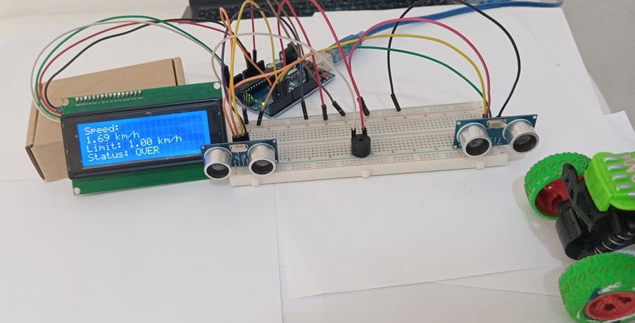
The calculated speed is displayed on the LCD screen along with the predefined speed limit and the system status. If the measured speed exceeds the limit, the buzzer is activated repeatedly and the display shows an “OVER” warning. Otherwise, the system indicates that the speed is acceptable (“OK”) and emits a short beep.
If an error occurs, such as an invalid time measurement, the program displays an error message on the screen. After each measurement cycle, the system pauses briefly before restarting and waiting for the next object.
1 comment

outdoor advertising flags near me 30-04-2626
Thanks very interesting blog!
Leave a comment
Passion for robotics

Recent tutorials
Robotics workshop

Polpular tutorials


Making robots

Most commented tutorials


Robotic arm

Categories
Smart Home